
Page 83 - Adsorbents fundamentals and applications
P. 83
68 PORE SIZE DISTRIBUTION
Original HK
1.6
Original HK–CY
Corrected HK
d(W/W 0 )/dL 0.8
1.2
Corrected HK–CY
0.4
0.0
2 3 4 5 6 7 8
Effective pore size (Å)
Figure 4.5. Pore size distribution of HGS-638 molecular sieve carbon as predicted by original
HK models and the corrected HK models for slit-shaped pores (Rege and Yang, 2000,
with permission).
1.4
Original HK
1.2
Original HK–CY
1.0 Corrected HK–CY
d(W/W 0 )/dL 0.8 Modified HK–CY
0.6
0.4
0.2
0.0
4 6 8 10 12 14 16 18
Effective pore size (Å)
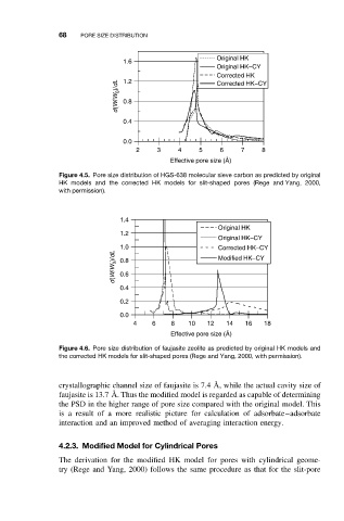
Figure 4.6. Pore size distribution of faujasite zeolite as predicted by original HK models and
the corrected HK models for slit-shaped pores (Rege and Yang, 2000, with permission).
crystallographic channel size of faujasite is 7.4 ˚ A, while the actual cavity size of
faujasite is 13.7 ˚ A. Thus the modified model is regarded as capable of determining
the PSD in the higher range of pore size compared with the original model. This
is a result of a more realistic picture for calculation of adsorbate–adsorbate
interaction and an improved method of averaging interaction energy.
4.2.3. Modified Model for Cylindrical Pores
The derivation for the modified HK model for pores with cylindrical geome-
try (Rege and Yang, 2000) follows the same procedure as that for the slit-pore