
Page 86 - Adsorption, Ion Exchange & Catalysis- 2007, Elsevier - Copy
P. 86
Else_AIEC-INGLE_cH003.qxd 7/13/2006 1:45 PM Page 82
82 3. Heterogeneous Processes and Reactor Analysis
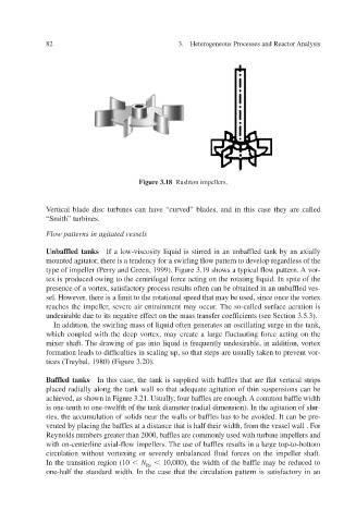
Figure 3.18 Rushton impellers.
ed”
v
Vertical blade disc turbines can hae “curv blades, and in this case they are called
“Smith” turbines.
Flow patterns in agitated vessels
Unbaffled tanks If a low-viscosity liquid is stirred in an unbaffled tank by an axially
mounted agitator, there is a tendency for a swirling flow pattern to develop regardless of the
type of impeller (Perry and Green, 1999). Figure 3.19 sho or- A v w pattern. ws a typical flo
tex is produced owing to the centrifugal force acting on the rotating liquid. In spite of the
presence of a vortex, satisf actory process results often can be obtained in an unbaffled ves-
sel. However, there is a limit to the rotational speed that may be used, since once the vortex
v
,
reaches the impeller seere air entrainment may occurThe so-called surface aeration is .
undesirable due to its negative effect on the mass transfer coefficients (see Section 3.5.3).
In addition, the swirling mass of liquid often generates an oscillating surge in the tank,
x,
orte
which coupled with the deep v may create a large fluctuating force acting on the
mixer shaft. The drawing of gas into liquid is frequently undesirable, in addition, v x orte
f formation leads to dificulties in scaling up, so that steps are usually taken to pre v ent v or-
tices (Treybal, 1980) (Figure 3.20).
Baffled tanks In this case, the tank is supplied with baffles that are flat vertical strips
placed radially along the tank wall so that adequate agitation of thin suspensions can be
wn in Figure 3.21. Usually, achieved, as shofour baffles are enough. A common baffle width
is one-tenth to one-twelfth of the tank diameter (radial dimension). In the agitation of slur-
ries, the accumulation of solids near the walls or baffles has to be aoided. It can be pre- v
vented by placing the baffles at a distance that is half their width, from the vessel wall . For
Reynolds numbers greater than 2000, baffles are commonly used with turbine impellers and
with on-centerline axial-flow impellers. The use of baffles results in a lar ge top-to-bottom
circulation without vxing or seerely unbalanced fluid forces on the impeller shaft.
orte
v
In the transition region (10 N 10,000), the width of the baffle may be reduced to
Re
one-half the standard width. In the case that the circulation pattern is satisfactory in an