
Page 114 - Advanced Design Examples of Seismic Retrofit of Structures
P. 114
106 Advanced Design Examples of Seismic Retrofit of Structures
L w
A 11 A 12 A 13 A 14 A 15 A 16
X
(A) i
c
ε 1
ε 2 ε 3
ε 4
(B) ε 5 ε u
ε 6
fy 1 fy 2 fy 3 fy 4
afm eq
(C) a
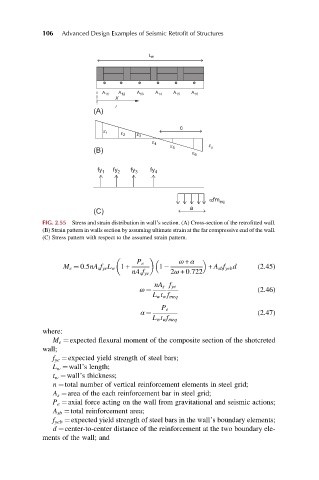
FIG. 2.55 Stress and strain distribution in wall’s section. (A) Cross-section of the retrofitted wall.
(B) Strain pattern in walls section by assuming ultimate strain at the far compressive end of the wall.
(C) Stress pattern with respect to the assumed strain pattern.
ω + α
P e
M e ¼ 0:5nA s f ye L w 1+ 1 + A sb f yeb d (2.45)
nA s f ye 2ω +0:722
nA s f ye
ω ¼ (2.46)
L w t w f meq
P e
α ¼ (2.47)
L w t w f meq
where:
M e ¼expected flexural moment of the composite section of the shotcreted
wall;
f ye ¼expected yield strength of steel bars;
L w ¼wall’s length;
t w ¼wall’s thickness;
n ¼total number of vertical reinforcement elements in steel grid;
A s ¼area of the each reinforcement bar in steel grid;
P e ¼axial force acting on the wall from gravitational and seismic actions;
A sb ¼total reinforcement area;
f yeb ¼expected yield strength of steel bars in the wall’s boundary elements;
d ¼center-to-center distance of the reinforcement at the two boundary ele-
ments of the wall; and