
Page 266 - Advanced Design Examples of Seismic Retrofit of Structures
P. 266
Example of a Steel Frame Building With Masonry Infill Walls Chapter 4 259
(A) (B)
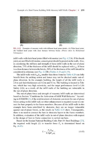
FIG. 4.22 Examples of masonry walls with different head joints details. (A) Filled head joints.
(B) Unfilled head joints with clear distance between bricks. (Photos taken by Mohammad
Yekrangnia.)
infill walls with their head joints filled with mortar (see Fig. 4.22A). If the heads
jointsarenotfilledwithmortar,cementgroutshouldbepouredonthewalls.Also,
in calculating the stiffness and strength of these infill walls in the out-of-plane
direction, 75% of the thickness of the infill should be replaced with t inf . If there
is a clear distance between the bricks, 50% of the thickness of the infill should be
considered in relations (see Fig. 4.22B) (Tables 4.18 and 4.19).
The infill walls with h inf /t inf smaller than those found in Table 4.20 can fully
benefit from the arching action and hence may not be checked under out-of-
plane direction. In the example building, the height of all the infill walls is
2.8m and their thicknesses are 0.2m and 0.3m. The building is located in Teh-
ran, which has very high seismicity, and the target performance level is Life
Safety (LS); as a result, all the infill walls of the building are vulnerable in
the out-of-plane direction.
The out-of-plane force and strength of masonry infill walls are determined
based on Section “Conditions for Activation of Infill Wall Behavior.” Accord-
ing to ICERIFB [2], if the reinforcement of shotcrete can resist the out-of-plane
forces acting on the infill wall, no other enhancement is required except to con-
nect the bars properly to the frame members. Because all the infill walls in this
example have been retrofitted by shotcrete, they are no longer vulnerable
against out-of-plane forces, as the results in Table 4.21 show. Consequently,
there is no need to connect the bars in shotcrete layers to the frame members.
In addition, evaluation of the infill walls in out-of-plane direction with respect
to the design of bars to frame connection is carried out here.
Based on the Iranian National Building Code; Part 10: Steel Buildings [23],
the required weld length (L) to transfer force F p is determined based on
Eq. (4.45):
F p A inf
L ¼ (4.45)
0:3ϕF ue a e