
Page 271 - Advanced Design Examples of Seismic Retrofit of Structures
P. 271
264 Advanced Design Examples of Seismic Retrofit of Structures
h inf
[2]
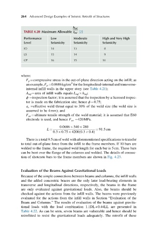
TABLE 4.20 Maximum Allowable t inf
Performance Low Moderate High and Very High
Level Seismicity Seismicity Seismicity
IO 14 13 8
LS 15 14 9
CP 16 15 10
where:
F p ¼compressive stress in the out-of-plane direction acting on the infill; as
2
an example, F p ¼0.0686kg/cm for the longitudinal-internal and transverse-
internal infill walls in the upper story (see Table 4.21);
A inf ¼area of infill walls equals L inf h inf ;
ϕ ¼inspection factor; it is assumed that the inspection by a licensed inspec-
tor is made on the fabrication site; hence ϕ¼0.75;
a e ¼effective weld throat equal to 30% of the weld size (the weld size is
assumed to be 4mm); and
F ue ¼ultimate tensile strength of the weld material; it is assumed that E60
electrode is used, and hence F ue ¼420MPa.
0:0686 540 280
L ¼ ¼ 91:5cm
ð
0:3 0:75 4200 0:3 0:4Þ
There is a total 9.5cm of weld with aforementioned specifications to transfer
to total out-of-plane force from the infill to the frame members. If 10 bars are
welded to the frame, the required weld length for each bar is 5cm. These bars
can be bent over the flange of the columns and welded. The details of connec-
tion of shotcrete bars to the frame members are shown in Fig. 4.23.
Evaluation of the Beams Against Gravitational Loads
Because of the simple connections between beams and columns, the infill walls
and the added concentric braces are the only later load-bearing elements in
transverse and longitudinal directions, respectively, the beams in the frame
are only evaluated against gravitational loads. Also, the beams should be
checked against the actions from the infill walls. The beams were previously
evaluated for the actions from the infill walls in Section “Evaluation of the
Beam and Columns.” The results of evaluation of the beams against gravita-
tional loads with the load combination 1.1DL+0.44LL are presented in
Table 4.22. As can be seen, seven beams are vulnerable and hence should be
retrofitted to resist the gravitational loads adequately. The retrofit of these