Page 316 - Advanced Design Examples of Seismic Retrofit of Structures
P. 316

Example of a Steel Frame Building Retrofitted Chapter  5 305


                                            635   b f
                                                                       (5.21)
                                       L C ¼ p ffiffiffiffiffi
                                               F y
                                           14 10 5
                                                                       (5.22)
                                      L C ¼
                                           d=A f   F y
             where:
                b f ¼width of the compression flange;
                A f ¼area of the compression flange; and
                d ¼height of the flexural member;
                As an example and for IPE 140 we have:
                                    635 7:3
                             635:b f
                               ffiffiffiffiffi ¼ p ffiffiffiffiffiffiffiffiffiffi ¼ 95:43 cmð  Þ
                        L C ¼ p
                                       2360
                               F y
                              14 10 5      14 10 5
                                                             ð
                                      ¼              ¼ 347:45 cmÞ
                        L C ¼
                              d=A f   F y  ð 14=8:2Þ 2360
                           ) L C ¼ min 95:43, 347:45ð  Þ ¼ 95:43 cmÞ
                                                        ð
                All the beams that carry gravity loads are braced, because the distance of the
             joists in the diaphragms is smaller than L c . For the beams that do not carry grav-
             ity loads, and where the conditions of braced section are not satisfied, the
             expected flexural capacity of the section, Q CE , shall be computed in accordance
             with Eq. (5.23):
                                    Q CE ¼ M CE ¼ 1:1F ye S            (5.23)
             where S ¼the elastic section modulus of a member.
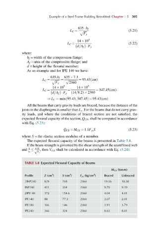
                The expected flexural capacity of the beams is presented in Table 5.8.
                If the beam strength is governed by the shear strength of the unstiffened web
                    418
             and  h    ffiffiffiffip , then V CE shall be calculated in accordance with Eq. (5.24):
                t w
                     F y
               TABLE 5.8 Expected Flexural Capacity of Beams
                                                              M CE (tonm)
                             3
                                                    2
                                       3
               Profile   Z (cm )   S (cm )   F ye (kg/cm )  Braced  Unbraced
               2INP240   829       708       2360         19.56    18.38
               INP240    411       354       2360         9.70     9.19
               2IPE140   172       154.6     2360         4.04     4.01
               IPE140    88        77.3      2360         2.07     2.01
               IPE180    166       146       2360         3.91     3.79
               IPE240    366       324       2360         8.63     8.41
   311   312   313   314   315   316   317   318   319   320   321