
Page 318 - Advanced Design Examples of Seismic Retrofit of Structures
P. 318
Example of a Steel Frame Building Retrofitted Chapter 5 307
TABLE 5.10 Lower-Bound Axial Capacity of Columns
F a Q CL
2
2
Profile r (cm) A (cm ) λ F.S. (kg/cm ) (ton)
2IPE140 5.74 32.8 65.33 1.84 1093.82 61.0
(Story-1)
2IPE140 5.74 32.8 58.36 1.82 1133.04 63.2
(Story-2)
2IPE160 6.57 40.2 57.07 1.81 1144.44 78.2
(Story-1)
2IPE160 6.57 40.2 50.98 1.80 1173.65 80.2
(Story-2)
2IPE160 6.57 100.2 57.07 1.81 1144.44 194.9
+2PL
(Story-1)
Q
Q y
b
a
1.0 C
B
D E c
A
q or D
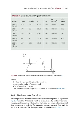
FIG. 5.10 Generalized force-deformation relation for steel elements or components [3].
where:
L ¼laterally unbraced length of the member;
r ¼governing radius of gyration; and
K ¼effective length factor.
The lower-bound axial capacity of columns is presented in Table 5.10.
5.6.2 Nonlinear Static Procedure
The complete load-deformation relationship of each component as depicted in
Fig. 5.10 shall be determined based on plastification by nonlinear moment-
curvature and interaction relationships for beams and beam-columns derived
from experiment or analysis. The values for expected strength, Q CE , shall be
the same as those used for linear procedures as specified in Section 5.7.1.