
Page 323 - Advanced Design Examples of Seismic Retrofit of Structures
P. 323
Linear interpolation between the values on lines a and b for both flange slenderness (first term) and web slenderness (second term) shall be performed,
Linear interpolation between the values on lines a and b for both flange slenderness (first term) and web slenderness (second term) shall be performed,
Radians
11θ y
11θ y
CP
4θ y
4θ y
– d
Angle,
Rotation
LS
9θ y
3θ y
3θ y
9θ y
– e
Plastic
0.25θ y
0.25θ y
0.25θ y
1θ y
IO
1θ y
Ratio
Strength
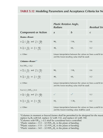
for [3] Components Steel Procedures-Structural Nonlinear Parameters Modeling 312 Criteria Acceptance Advanced Design Examples of Seismic Retrofit of Structures 1.2θ y 1.2θ y 0.25θ y Linear interpolation between the values on lines a and b for both flange slenderness (first term) and web slenderness (second term) shall be perfor
Residual
Criteria c 0.6 0.2 0.6 0.2 0.2 0.2 for designed 190.
Acceptance Angle, b 11θ y 6θ y and the lower resulting value shall be used. 11θ y 6θ y and the lower resulting value shall be used. – d 1.5θ y and the lowest resulting value shall be used. be to with 65 controlled. bending. bending. bending.
and Rotation permitted be replace and force of plane of plane of plane
Parameters Plastic Radians a 9θ y 4θ y 9θ y 4θ y – c 1θ y shall frames 110, with 52 considered be the in P/P CL )θ y the in P/P CL )θ y the in P/P CL )θ y
Modeling Action or 418 h p ffiffiffiffiffi F ye 640 ffiffiffiffiffi F ye 300 h p ffiffiffiffiffi F ye 460 ffiffiffiffiffi F ye 260 h p ffiffiffiffiffi F ye 400 ffiffiffiffiffi F ye braced or moment replace b/t, shall P/P CL >0.5 rotation¼11(1 5/3 rotation¼17(1 5/3 rotation¼14(1 5/3
5.12 ffiffiffiffiffi and t w F ye h p ffiffiffiffiffi or t w F ye Columns—flexure a,b and ffiffiffiffiffi t w F ye h p or ffiffiffiffiffi t w F ye For 0.2 P/P CL 0.5 ffiffiffiffiffi and t w F ye h p ffiffiffiffiffi or t w F ye in with b t /2t f with
TABLE Component Beams—flexure 52 b f a: 2t f p 65 b f b: 2t f p c: Other For P/P CL <0.2 52 b f a: 2t f p 65 b f b: 2t f p c: Other b f 52 a: 2t f p b f 65 b: 2t f p c: Other a Columns replace b Columns c Plastic d Plastic e Plastic