
Page 317 - Advanced Design Examples of Seismic Retrofit of Structures
P. 317
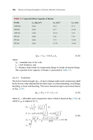
306   Advanced Design Examples of Seismic Retrofit of Structures


              TABLE 5.9 Expected Shear Capacity of Beams
                                       2
                                                        2
              Profile          F ye (kg/cm )      A w (cm )        V CE (ton)
              2INP240          2360               33.4             47.3
              INP240           2360               16.7             23.64
              2IPE140          2360               10.52            14.9
              IPE140           2360               5.26             7.44
              IPE180           2360               7.73             10.94
              IPE240           2360               11.78            16.68


                                                                       (5.24)
                                  Q CE ¼ V CE ¼ 0:6:F yE :A w
            where:
               A w ¼nominal area of the web;
               t w ¼web thickness; and
               h ¼distance from inside of compression flange to inside of tension flange.
               The expected shear capacity of beams is presented in Table 5.9.


            5.6.1.2 Columns
            The lower-bound strength, Q CL , of steel columns under axial compression shall
            be the lowest value obtained for the limit states of column buckling, local flange
            buckling, or local web buckling. This lower-bound strength is determined based
            on Eq. (5.25).
                                  Q CL ¼ P CL ¼ 1:7 F a  A             (5.25)

            where F a ¼allowable axial compressive stress which is based on Eq. (5.26),in
            which F yLB is replaced by F y .
                                "          2  #
                              1     1   λ
                         F a ¼   1             F y
                             F:S    2 C C
                                           λ          λ
                                                          3
                         F   S ¼ 1:67 + 0:375   0:125
                                          C C         C C              (5.26)
                             s ffiffiffiffiffiffiffiffiffiffiffiffiffi
                                       r ffiffiffiffiffiffiffiffiffiffiffiffiffiffiffiffiffiffiffiffiffiffiffiffiffiffiffiffiffiffiffiffiffiffiffi 6
                                 2
                                             2
                               2π   E    2 π  2:1 10
                         C C ¼       ¼                  ¼ 131:94
                                 F y          2275
                            KL
                         λ ¼
                             r