
Page 429 - Advanced Design Examples of Seismic Retrofit of Structures
P. 429
Example of a Steel Frame Building Retrofitted Chapter 5 377
PL200x80x10 (New)
7(New)
STIFFENER 150
2x2x1 / 2PL100x80x10 (New)
STIFFENER 7(New) 2IPE160+
850 2PL 250x10 (New)
A A
– –
2UNP160[BOX] (NEW)
7(New)
300 275
PL–1
850x550x10 (New)
50
7(New)
PL400x80x10 (New)
STIFFENER 400 7(New)
DETAIL A
–
2x2x1/2PL100x80x10 (New)
150 400
2UNP160[BOX] (NEW)
7(New)
150 300 for Br.
2IPE160+
2PL 250x10 (New)
PL–1
850x550x10(New)
7(New) PL–1 7(New)
700 400 for Stiff. 850x550x10 (New)
PL400x80x10 (New)
7(New)
STIFFENER 850
SECTION
A
–
SPACER
PL 200x100x10@750mm (New)
2UNP160[BOX] (New)
B 7(New)
–
7(New) 2UNP160[BOX] (New)
100
B 7(New)
–
300
2UNP160[BOX] (New)
SPACER
PL 200x100x10@750mm (New)
7(New)
2UNP160[BOX] (New)
2UNP160[BOX] (New)
7–100(New) PL 800x500x10 (New)
SECTION B DETAIL
– D
–
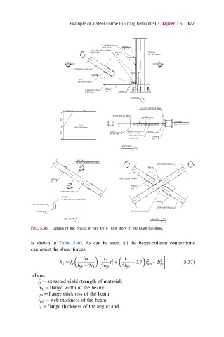
FIG. 5.41 Details of the braces in bay J/7-8 floor story in the main building.
is shown in Table 5.40. As can be seen, all the beam-column connections
can resist the shear forces.
b fb L 2 L 2 2
R 1 ¼ f y t + +0:7 t +2t (5.37)
1 wb fb
b fb 2t 1 2b fb 2b fb
where:
f y ¼expected yield strength of material;
b fb ¼flange width of the beam;
t fb ¼flange thickness of the beam;
t wb ¼web thickness of the beam;
t 1 ¼flange thickness of the angle; and