
Page 430 - Advanced Design Examples of Seismic Retrofit of Structures
P. 430
378 Advanced Design Examples of Seismic Retrofit of Structures
7(New)
150–400
2UNP80[BOX] (NEW) PL 250x100x8@500mm
7(New)
PL140x80x10 (New) 140 7(NEW)
STIFFENER
7(New)
340 2x1/2PL100x80x10 (New)
STIFFENER
7(New)
PL–3 100 7(NEW)
400x400x10(New)
PL140x80x10 (New) 170
STIFFENER 7(New) 2INP240 IPE140
140
PL420x350x10 (New) 7(New) 7(New)
PL540x400x10 (New) 340 7(New)
7(New) 340
7(New) 2IPE140
350
PL250x80x10 (New)
7(New) 7(NEW) STIFFENER 170
400 PL–3
PL200x80x10 (New) 400x400x10(New) 7(New) 2x1/2PL100x80x10 (New)
STIFFENER
STIFFENER 7(New)
200 140
7(New)
390 170 PL140x80x10 (New)
STIFFENER 2IPE160
2x1/2PL100x80x10 (New) 7(New) 7(New)
STIFFENER 100 340 PL 250x100x8@500mm
7(New)
PL–2 300 2IPE160+ 2UNP80[BOX] (New)
450x450x10 (New) 2PL 250x10 (New)
PL200x80x10 (New)
STIFFENER
7(New) DETAIL C
200 –
7(New)
390
2UNP160[BOX] (NEW)
90 250
DETAIL
B
– 90
PL–3 340
400x400x10(New)
250
390 60
60
325 60 340 60
PL–2
450x450x10(New) 390
125
125 325
SPACER 2UNP80[BOX] (NEW)
PL 120x100x10@750mm (NEW)
7(New)
C
–
2UNP80[BOX] (NEW)
7(New)
100
7(New)
C 100
–
2UNP80[BOX] (NEW)
SPACER
PL 120x100x10@750mm (NEW) 7(New)
2UNP80[BOX] (NEW) 2UNP80[BOX] (NEW)
PL 300x200x10 (NEW)
7(New)
100
DETAIL
SECTION E
C –
–
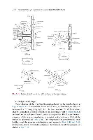
FIG. 5.42 Details of the braces in bay J/7-8 first story in the main building.
L ¼length of the angle.
The evaluation of the retrofitted foundation based on the details shown in
Figs. 5.46 and 5.47 is made here. Based on ASCE 41, if the base of the structure
is assumed to be completely rigid, then the base reactions for all foundations
shall be classified as force controlled, in accordance with Section 5.5.5.2,
and shall not exceed upper-bound component capacities. The J-factor in deter-
mination of the actions calculations is selected as the minimum DCR of the
braces, as presented in Table 5.41. The soil pressure in the retrofitted main
building and the required reinforcement are shown in Figs. 5.48 and 5.49,
respectively. Some construction stages in the foundation retrofit process are
shown in Fig. 5.50.