
Page 461 - Advanced Design Examples of Seismic Retrofit of Structures
P. 461
Examples of Nonengineered Buildings Chapter 6 407
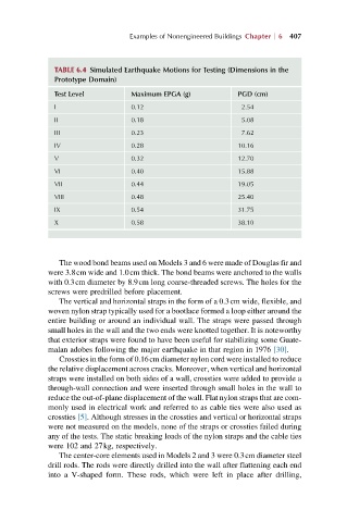
TABLE 6.4 Simulated Earthquake Motions for Testing (Dimensions in the
Prototype Domain)
Test Level Maximum EPGA (g) PGD (cm)
I 0.12 2.54
II 0.18 5.08
III 0.23 7.62
IV 0.28 10.16
V 0.32 12.70
VI 0.40 15.88
VII 0.44 19.05
VIII 0.48 25.40
IX 0.54 31.75
X 0.58 38.10
The wood bond beams used on Models 3 and 6 were made of Douglas fir and
were 3.8cm wide and 1.0cm thick. The bond beams were anchored to the walls
with 0.3cm diameter by 8.9cm long coarse-threaded screws. The holes for the
screws were predrilled before placement.
The vertical and horizontal straps in the form of a 0.3cm wide, flexible, and
woven nylon strap typically used for a bootlace formed a loop either around the
entire building or around an individual wall. The straps were passed through
small holes in the wall and the two ends were knotted together. It is noteworthy
that exterior straps were found to have been useful for stabilizing some Guate-
malan adobes following the major earthquake in that region in 1976 [30].
Crossties in the form of 0.16cm diameter nylon cord were installed to reduce
the relative displacement across cracks. Moreover, when vertical and horizontal
straps were installed on both sides of a wall, crossties were added to provide a
through-wall connection and were inserted through small holes in the wall to
reduce the out-of-plane displacement of the wall. Flat nylon straps that are com-
monly used in electrical work and referred to as cable ties were also used as
crossties [5]. Although stresses in the crossties and vertical or horizontal straps
were not measured on the models, none of the straps or crossties failed during
any of the tests. The static breaking loads of the nylon straps and the cable ties
were 102 and 27kg, respectively.
The center-core elements used in Models 2 and 3 were 0.3cm diameter steel
drill rods. The rods were directly drilled into the wall after flattening each end
into a V-shaped form. These rods, which were left in place after drilling,