
Page 465 - Advanced Design Examples of Seismic Retrofit of Structures
P. 465
410 Advanced Design Examples of Seismic Retrofit of Structures
Horizontal strap
around exterior
Partial wood
diaphragm
Through-wall ties
around the horizontal
strap and through
joists or around
ledger (nylon string)
(A) (B)
(C) (D)
(E) (F)
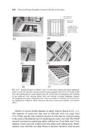
FIG. 6.11 Retrofit measures on Model 7 roof. (A) Attic-floor framing and partial diaphragm,
made of wood. (B) Attic plan, showing retrofit measures applied at floor level. (C) Inside of attic
floor, showing through-ties connecting joist and wall. (D) Roof line of load-bearing wall. (E) Detail
at east gable-end wall, showing anchor bolts and one-half of partial diaphragm exposed.
(F) Completed roof system. (Adapted from E.L. Tolles, E.E. Kimbro, F.A. Webster, W.S. Ginell, Seis-
mic Stabilization of Historic Adobe Structures, The Getty Conservation Institute, Los Angeles,
2000.)
Details of vertical retrofit elements on adobe wall are shown in Fig. 6.14.
The diameter of center-core rods used in full-scale walls can range from
12 to 25mm, and the rods should be inserted in holes that are sized according
to the needs of the material used for anchoring the center-core rods. The GSAP
research was based on a prototype adobe wall that was 41cm thick, and 17mm
diameter center-core rods worked well even when used without grout. Small-
diameter rods and holes less than 50mm in diameter should be used because