
Page 470 - Advanced Design Examples of Seismic Retrofit of Structures
P. 470
Examples of Nonengineered Buildings Chapter 6 413
Wood top plate
Wood top plate
Vertical nylon straps
Center-core rods
Nylon
crossties
Oversized holes
Adobe for placement of
Adobe wall center-core rods
wall
Buckles
Plastic pipes
at base of wall Drill holes to
foundation level
(A) (B)
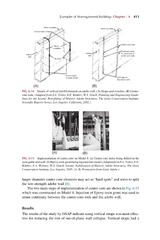
FIG. 6.14 Details of vertical retrofit elements on adobe wall. (A) Straps and crossties. (B) Center-
core rods. (Adapted from E.L. Tolles, E.E. Kimbro, W.S. Ginell, Planning and Engineering Guide-
lines for the Seismic Retrofitting of Historic Adobe Structures, The Getty Conservation Institute,
Scientific Reports Series, Los Angeles, California, 2002.)
(A) (B)
FIG. 6.15 Implementation of center-core on Model 8. (a) Center-core holes being drilled in the
west gable-end wall. (b) Epoxy resin grout being injected into model. (Adapted from E.L. Tolles, E.E.
Kimbro, F.A. Webster, W.S. Ginell, Seismic Stabilization of Historic Adobe Structures, The Getty
Conservation Institute, Los Angeles, 2000. (A, B) Permission from Getty Adobe.)
larger-diameter center-core elements may act as “hard spots” and serve to split
the low-strength adobe wall [6].
The two main steps of implementation of center-core are shown in Fig. 6.15
which was constructed on Model 8. Injection of Epoxy resin grout was used to
attain continuity between the center-core rods and the adobe wall.
Results
The results of the study by GSAP indicate using vertical straps was most effec-
tive for reducing the risk of out-of-plane wall collapse. Vertical straps had a