
Page 475 - Advanced Design Examples of Seismic Retrofit of Structures
P. 475
418 Advanced Design Examples of Seismic Retrofit of Structures
The retrofit system used on Model 8 was modified slightly to try to decrease
the amount of offset at horizontal cracks. The East wall (Fig. 6.20C) had vertical
straps, and the wall crossties were spaced closely together to limit the relative
displacement between adjacent blocks. The displacements in the gable-end wall
were limited to small amounts, which was an improvement over the perfor-
mance of Model 7, but was not as dramatic as that achieved by the installation
of center-core rods.
The performance of the West wall of Model 8 proved the effectiveness of
center-core rods in reducing the offset across cracks during out-of-plane ground
motions (Fig. 6.20D). Most of this wall, which was retrofitted with epoxied
center-core rods, experienced minimal cracks and no visible offsets across
center-core rods. On the other hand, severe damage to this wall occurred near
the base in the area where the center-core rods did not extend; this indicates
considerable energy dissipation in the areas outside of the center-core rods.
If the center-core rods had extended into the foundation, there may have been
additional damage in the upper part of the wall, since there would have been no
clear area for energy dissipation [5].
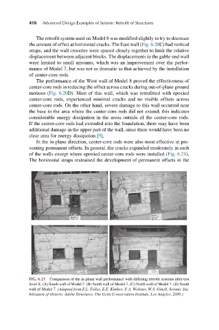
In the in-plane direction, center-core rods were also most effective at pre-
venting permanent offsets. In general, the cracks expanded moderately in each
of the walls except where epoxied center-core rods were installed (Fig. 6.21).
The horizontal straps restrained the development of permanent offsets in the
(A) (B)
(C) (D)
FIG. 6.21 Comparison of the in-plane wall performance with differing retrofit systems after test
level X. (A) South wall of Model 7. (B) North wall of Model 7. (C) North wall of Model 7. (D) South
wall of Model 7. (Adapted from E.L. Tolles, E.E. Kimbro, F.A. Webster, W.S. Ginell, Seismic Sta-
bilization of Historic Adobe Structures, The Getty Conservation Institute, Los Angeles, 2000.)