
Page 472 - Advanced Design Examples of Seismic Retrofit of Structures
P. 472
Examples of Nonengineered Buildings Chapter 6 415
(A) (B)
(C) (D)
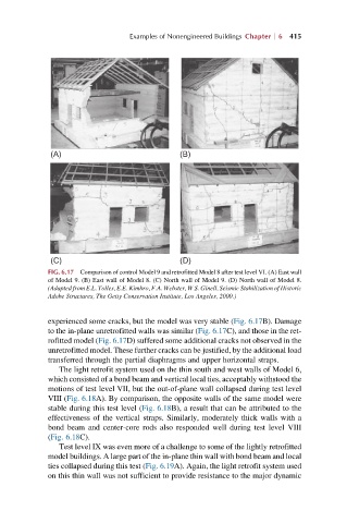
FIG. 6.17 Comparison of control Model 9 and retrofitted Model 8 after test level VI. (A) East wall
of Model 9. (B) East wall of Model 8. (C) North wall of Model 9. (D) North wall of Model 8.
(Adapted from E.L. Tolles, E.E. Kimbro, F.A. Webster, W.S. Ginell, Seismic Stabilization of Historic
Adobe Structures, The Getty Conservation Institute, Los Angeles, 2000.)
experienced some cracks, but the model was very stable (Fig. 6.17B). Damage
to the in-plane unretrofitted walls was similar (Fig. 6.17C), and those in the ret-
rofitted model (Fig. 6.17D) suffered some additional cracks not observed in the
unretrofitted model. These further cracks can be justified, by the additional load
transferred through the partial diaphragms and upper horizontal straps.
The light retrofit system used on the thin south and west walls of Model 6,
which consisted of a bond beam and vertical local ties, acceptably withstood the
motions of test level VII, but the out-of-plane wall collapsed during test level
VIII (Fig. 6.18A). By comparison, the opposite walls of the same model were
stable during this test level (Fig. 6.18B), a result that can be attributed to the
effectiveness of the vertical straps. Similarly, moderately thick walls with a
bond beam and center-core rods also responded well during test level VIII
(Fig. 6.18C).
Test level IX was even more of a challenge to some of the lightly retrofitted
model buildings. A large part of the in-plane thin wall with bond beam and local
ties collapsed during this test (Fig. 6.19A). Again, the light retrofit system used
on this thin wall was not sufficient to provide resistance to the major dynamic