
Page 476 - Advanced Design Examples of Seismic Retrofit of Structures
P. 476
Examples of Nonengineered Buildings Chapter 6 419
walls but still allowed displacements of the blocks. Stiffer straps may have been
used to provide greater restraint against damage, but two factors would need to
be taken into account: (1) a failure plane might develop just above the strap that
would permit slippage; or (2) the strap may dig into the adobe material and
loosen, even with a stiffer strap. To try to control the latter, a wire-mesh screen
was added at the exposed corners. However, the straps were still able to dig
into the adobe at the through-wall holes. Minimal damage was observed in
the in-plane wall of Model 9, where the vertical center-core rods were used
(Fig. 6.21D) [5].
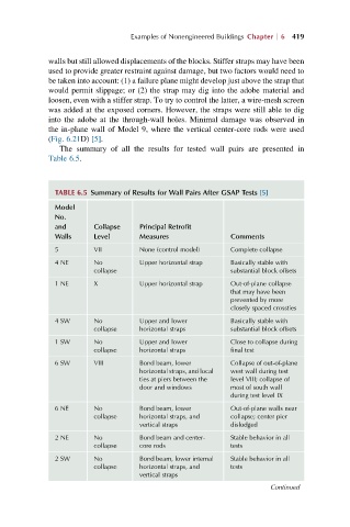
The summary of all the results for tested wall pairs are presented in
Table 6.5.
TABLE 6.5 Summary of Results for Wall Pairs After GSAP Tests [5]
Model
No.
and Collapse Principal Retrofit
Walls Level Measures Comments
5 VII None (control model) Complete collapse
4NE No Upper horizontal strap Basically stable with
collapse substantial block offsets
1 NE X Upper horizontal strap Out-of-plane collapse
that may have been
prevented by more
closely spaced crossties
4SW No Upper and lower Basically stable with
collapse horizontal straps substantial block offsets
1SW No Upper and lower Close to collapse during
collapse horizontal straps final test
6 SW VIII Bond beam, lower Collapse of out-of-plane
horizontal straps, and local west wall during test
ties at piers between the level VIII; collapse of
door and windows most of south wall
during test level IX
6NE No Bond beam, lower Out-of-plane walls near
collapse horizontal straps, and collapse; center pier
vertical straps dislodged
2NE No Bond beam and center- Stable behavior in all
collapse core rods tests
2SW No Bond beam, lower internal Stable behavior in all
collapse horizontal straps, and tests
vertical straps
Continued