
Page 498 - Advanced Design Examples of Seismic Retrofit of Structures
P. 498
Examples of Nonengineered Buildings Chapter 6 441
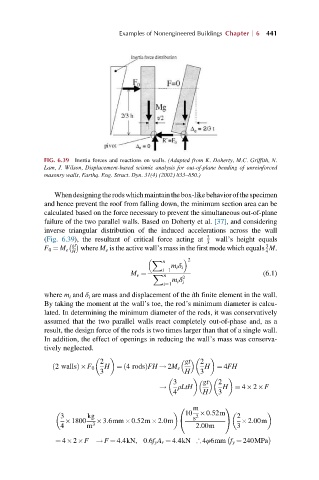
FIG. 6.39 Inertia forces and reactions on walls. (Adapted from K. Doherty, M.C. Griffith, N.
Lam, J. Wilson, Displacement-based seismic analysis for out-of-plane bending of unreinforced
masonry walls, Earthq. Eng. Struct. Dyn. 31(4) (2002) 833–850.)
Whendesigningtherodswhichmaintainthebox-likebehaviorofthespecimen
and hence prevent the roof from falling down, the minimum section area can be
calculated based on the force necessary to prevent the simultaneous out-of-plane
failure of the two parallel walls. Based on Doherty et al. [37], and considering
inverse triangular distribution of the induced accelerations across the wall
(Fig. 6.39), the resultant of critical force acting at 2 wall’s height equals
gt 3
3
F 0 ¼ M e H where M e is the active wall’s mass in the first mode which equals M.
4
2
X n
m i δ i
i¼1
M e ¼ X n (6.1)
m i δ 2
i¼1 i
where m i and δ i are mass and displacement of the ith finite element in the wall.
By taking the moment at the wall’s toe, the rod’s minimum diameter is calcu-
lated. In determining the minimum diameter of the rods, it was conservatively
assumed that the two parallel walls react completely out-of-phase and, as a
result, the design force of the rods is two times larger than that of a single wall.
In addition, the effect of openings in reducing the wall’s mass was conserva-
tively neglected.
gt
2 2
ð 2 wallsÞ F 0 H ¼ 4 rodsÞFH ! 2M e H ¼ 4FH
ð
3 H 3
gt
3 2
! ρLtH H ¼ 4 2 F
4 H 3
m
0 1
10 0:52m
3 kg s 2 2
1800 3:6mm 0:52m 2:0m @ A 2:00m
4 m 3 2:00m 3
¼ 4 2 F ! F ¼ 4:4kN, 0:6f y A r ¼ 4:4kN ;4φ6mm f y ¼ 240MPa