
Page 499 - Advanced Design Examples of Seismic Retrofit of Structures
P. 499
442 Advanced Design Examples of Seismic Retrofit of Structures
(A) (B)
(C) (D)
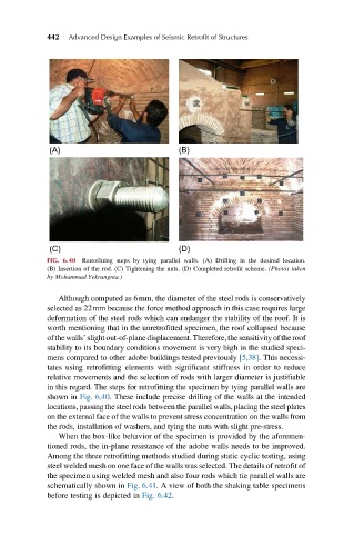
FIG. 6.40 Retrofitting steps by tying parallel walls. (A) Drilling in the desired location.
(B) Insertion of the rod. (C) Tightening the nuts. (D) Completed retrofit scheme. (Photos taken
by Mohammad Yekrangnia.)
Although computed as 6mm, the diameter of the steel rods is conservatively
selected as 22mm because the force method approach in this case requires large
deformation of the steel rods which can endanger the stability of the roof. It is
worth mentioning that in the unretrofitted specimen, the roof collapsed because
ofthewalls’slightout-of-planedisplacement.Therefore,the sensitivity oftheroof
stability to its boundary conditions movement is very high in the studied speci-
mens compared to other adobe buildings tested previously [5,38].This necessi-
tates using retrofitting elements with significant stiffness in order to reduce
relative movements and the selection of rods with larger diameter is justifiable
in this regard. The steps for retrofitting the specimen by tying parallel walls are
shown in Fig. 6.40. These include precise drilling of the walls at the intended
locations, passing the steel rods between the parallel walls, placing the steel plates
on the external face of the walls to prevent stress concentration on the walls from
the rods, installation of washers, and tying the nuts with slight pre-stress.
When the box-like behavior of the specimen is provided by the aforemen-
tioned rods, the in-plane resistance of the adobe walls needs to be improved.
Among the three retrofitting methods studied during static cyclic testing, using
steel welded mesh on one face of the walls was selected. The details of retrofit of
the specimen using welded mesh and also four rods which tie parallel walls are
schematically shown in Fig. 6.41. A view of both the shaking table specimens
before testing is depicted in Fig. 6.42.