
Page 72 - Advanced Design Examples of Seismic Retrofit of Structures
P. 72
64 Advanced Design Examples of Seismic Retrofit of Structures
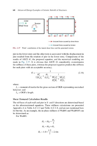
COM
Torsion
Shear force
COR
Induced force caused by shear force
Induced force caused by torsion
FIG. 2.37 Walls’ contribution of the lateral shear force and the generated torsion.
pier in the lower story and the other term is associated with the displacement in
pier resulted from the rotation of pier in the lower story. Comparisons of the
results of ASCE 41, the proposed equation, and the numerical modeling are
made in Fig. 2.37. It is obvious that ASCE 41 considerably overestimates
the stiffness of these piers, whereas the proposed equation predicts the stiffness
for such piers with an acceptable accuracy.
1
K ¼ 3 (2.16)
H 1
e H e
+ +
12E m I g A v G m 4E m I g 6E m I o
+
2 2
H H e H L o
s s
where:
I o ¼moment of inertia for the gross section of OKB representing uncracked
behavior; and
L o ¼OKB’s length.
Shear Demand Calculation Results
The stiffness of each wall and pier in X- and Y-directions are determined based
on the aforementioned equations. These stiffness calculations are presented
Appendix-A in Table A-C-2-3 and Table A-C-2-4, and are not mentioned here
for brevity. As an example, the in-plane stiffness of Wall#1 and Wall#105 can
be determined as:
For Wall#1:
H o
H e ¼ H W +
2
H s ¼ H W + H o
1:2
H e ¼ 1:8+ ¼ 2:4m
2