Page 77 - Advanced Design Examples of Seismic Retrofit of Structures
P. 77

Example of a Two-Story Unreinforced Masonry Building Chapter  2 69


                                               0.92  0.64  0.61  0.56  0.56  0.99
              1   0.55  0.57  0.57  0.57  0.56  0.82  0.28
                                                1.89 B  1.9 T  1.97 T
                                                                         2.49 B
                                            1.77 T
                         1.77 T    1.77 T            0.45
               2.01 B                      0.39 0.34    1.04 R   1.88 B
                1.29 B   1.42 B    1.4 B  0.74
                                                    0.59  1.34 B   1.12 B
             0.62  1.36 B    1.36 B   1.27 B
                                                                         2.72 B
                                                     1.65 B
              2.01 B    1.77 T    1.77 T    1.13 B
                                           2.22 R 1.47 R 2.22 R 0.9  0.55  0.54  0.53  0.94
              1.03 R 0.57  0.59  0.58  0.58  0.58  1.03 R
             (A)
                                               0.84  0.96  0.59  0.79  0.79  0.91
             0.92  0.8  0.73  0.71  0.73  0.86  0.7  0.3
                                               1.89 B  1.98 B  2.07 B
                                                                         2.47 B
                                           1.82 B
                        1.82 B    1.82 B
              1.94 B                       0.69 0.52  0.61  0.76  1.21 B
                1.1 B     1.1 B    1.09 B  1.08 R
                                                    0.88  1.02 B   1.01 B
             0.93  1.06 B    1.06 B   1.07 B
                                                                         2.51 B
                                                               3.35 B
                                                     1.25 B
              1.94 B    1.82 B    1.82 B   1.06 B
                                          1.19 R  1.39 R 1.19R  0.84  0.68  0.72  0.77  0.86
             0.95  0.84  0.73  0.77  0.79  0.77  0.95
             (B)
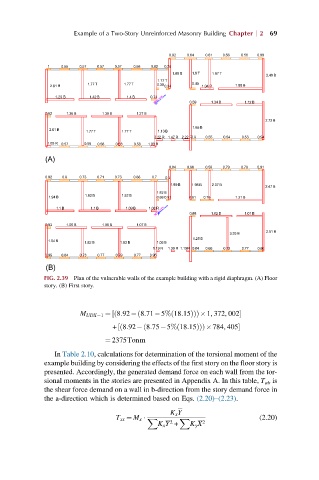
             FIG. 2.39 Plan of the vulnerable walls of the example building with a rigid diaphragm. (A) Floor
             story. (B) First story.


                               ½
                       M UDX 1 ¼ 8:92  8:71 5% 18:15ÞÞÞ 1, 372, 002Š
                                               ð
                                ð
                                      ð
                                                 ð
                                 ð
                                 ½
                                        ð
                               +8:92  8:75 5% 18:15ÞÞÞ 784, 405Š
                             ¼ 2375Tonm
                In Table 2.10, calculations for determination of the torsional moment of the
             example building by considering the effects of the first story on the floor story is
             presented. Accordingly, the generated demand force on each wall from the tor-
             sional moments in the stories are presented in Appendix A. In this table, T ab is
             the shear force demand on a wall in b-direction from the story demand force in
             the a-direction which is determined based on Eqs. (2.20)–(2.23).
                                               K x Y
                                                                       (2.20)
                                T xx ¼ M x   X  2  X    2
                                            K x Y +  K y X
   72   73   74   75   76   77   78   79   80   81   82