
Page 105 - Advanced Gas Turbine Cycles
P. 105
78 Advanced gas turbine cycles
50
49
-48
*
g 47
E!
0
k46
W
4
r
+ = 30 one step cooling
W -A- r = 35 one step cooling
>
044
4 = 40 one step cooling
r
43
42
200 300 400 500 600 700 800 900 1000 1100 1200
SPECIFIC WORK [kJlkg exhaust gas]
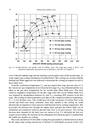
Fig. 5.4. Overall efficiency and specific work for [cB'l'lrcl plant with single-step cooling of NGVs, with
combustion temperature and pressure ratio as parameters (after Ref. [5], Chapter 4).
rows of the first turbine stage and the stationary nozzle guide vanes of the second stage. As
in the single-step cooling calculations described before, film cooling was assumed and the
Holland and Thake approach was followed to determine the cooling air required in each of
these blade rows.
From the combustion temperature T,,, and an assumed first stage pressure ratio (3:1),
the 'mixed out' gas temperature at exit from the first stage (TEI) was obtained and this was
taken as the gas entry temperature for the second stage (third blade row). The entry
(relative) stagnation temperature for the first stage rotor (the second turbine blade row)
was obtained by interpolation between TEI and Tcot, assuming 50% reaction in the first
stage. The cooling air inlet temperature was taken as the compressor delivery temperature,
Tci = T2 for all three rows. This would have led to the estimation of coolant flow in the
second and third rows being somewhat more than needed as the cooling air could
theoretically be tapped at a lower pressure (and therefore lower cooling temperature). But
in practice the pressure loss through the supply ducts and past the turbine disks can be
substantial and compressor delivery pressure may have to be used anyway. The cooling
fractions thus obtained for the three rows are shown in Fig. 5.5; obviously the first row
requires most cooling, the fractions for the subsequent rows decrease and it is assumed that
the fourth row requires no cooling.
The cycle calculations for this multi-cooling then proceeded in a similar fashion to those
for the single-step cooling calculations of Section 5.4 (full details are given in Ref. [2]).