
Page 110 - Advanced Gas Turbine Cycles
P. 110
Chapter 5. Full calculations of plant eficiency 83
2 0.4000 ,
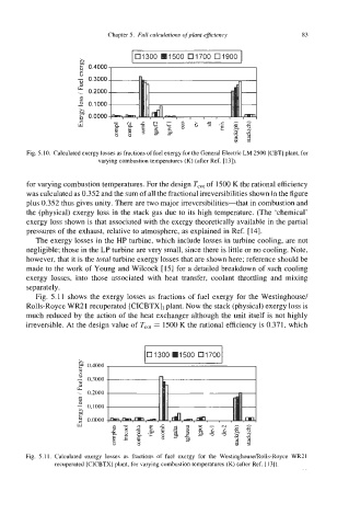
Fig. 5.10. Calculated exergy losses as fractions of fuel exergy for the General Electric LM 2500 [CBT] plant, for
varying combustion temperatures (K) (after Ref. [13]).
for varying combustion temperatures. For the design T,,, of 1500 K the rational efficiency
was calculated as 0.352 and the sum of all the fractional irreversibilities shown in the figure
plus 0.352 thus gives unity. There are two major irreversibilities-that in combustion and
the (physical) exergy loss in the stack gas due to its high temperature. (The ‘chemical’
exergy loss shown is that associated with the exergy theoretically available in the partial
pressures of the exhaust, relative to atmosphere, as explained in Ref. [ 141.
The exergy losses in the HP turbine, which include losses in turbine cooling, are not
negligible; those in the LP turbine are very small, since there is little or no cooling. Note,
however, that it is the total turbine exergy losses that are shown here; reference should be
made to the work of Young and Wilcock [15] for a detailed breakdown of such cooling
exergy losses, into those associated with heat transfer, coolant throttling and mixing
separately.
Fig. 5.1 1 shows the exergy losses as fractions of fuel exergy for the Westinghouse/
Rolls-Royce WR21 recuperated [CICBTX], plant. Now the stack (physical) exergy loss is
much reduced by the action of the heat exchanger although the unit itself is not highly
irreversible. At the design value of T,,, = 1500 K the rational efficiency is 0.371, which
0.4000
0.2000
0. I owl
0.oooO
Fig. 5.1 1. Calculated exergy losses as fractions of fuel exergy for the WestinghousedRolls-Royce WR21
recuperated [CICBTX] plant, for varying combustion temperatures (K) (after Ref. [13]).