
Page 153 - Advanced Gas Turbine Cycles
P. 153
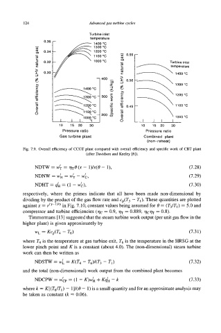
1 24                      Advanced gas turbine cycles

                                     Turbine inlet
               -   0.36               temperature
                                       1400 "C
                OY
               -   0.34
                I
               2   0.32                                  -Turbine          inlet
                Q                                                     temperature
                c
               $   0.30                                                 1400 'C
               E                              a
                0
                ZI                                                      1300 "C
                c
               .-                  1400 'C    Y
                0)
               $                              Y                         1200 "C
                0
               -  -                           3
                2                             0                         1100°C
                Q)                            0
               6                              Q
                                                         u
                                   1000 "C                              1000 "C
                         10   15  20   30                  10   15  20   30
                           Pressure ratio                   Pressure ratio
                         Gas turbine plant                  Combined  plant
                                                             (non-reheat)
          Fig. 7.9. Overall efficiency of CCGT plant compared with overall efficiency and specific work of CBT plant
                                    (after Davidson and Keeley [6]).

               NDTW = W;  = we(n - i)/~(e - I),                               (7.28)
                                    I
               NDNW = W'H  = W'T  - wc,                                       (7.29)
               NDHT = dH = (1 - Wk),                                          (7.30)
          respectively, where  the  primes indicate  that  all have  been  made non-dimensional by
          dividing by the product of the gas flow rate and c (T  - Tl). These quantities are plotted
                                                   p.
          against n = r-(y-')'y  in Fig. 7.10, constant values being assumed for 8 = (T3/Tl) = 5.0 and
          compressor and turbine efficiencies (qc = 0.9,   = 0.889, ww = 0.8).
             Timmermans [ 131 suggested that the steam turbine work output (per unit gas flow in the
          higher plant) is given approximately by
               WL  = KcP(T4 - T6)                                             (7.31)
          where T4 is the temperature at gas turbine exit, T6 is the temperature in the HRSG at the
          lower pinch point and K is a constant (about 4.0). The (non-dimensional) steam turbine
          work can then be written as

               NDsTW  = dL = K(T4 - T6)/(T3 - TI)                             (7.32)
          and the total (non-dimensional) work output from the combined plant becomes
               NDCPW = wbp  = (1 - K)wh + Kqh - k                             (7.33)
          where k = K[(T6/T,) - 1]/(8 - 1) is a small quantity and for an approximate analysis may
          be taken as constant (k = 0.06).