
Page 152 - Advanced Gas Turbine Cycles
P. 152
Chapter 7. The combined cycle gas turbine (CCGT) 123
Exhaust DtFH
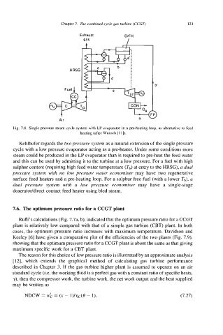
Fig. 7.8. Single pressure steam cycle system with LP evaporator in a pre-heating loop, as alternative to feed
heating (after Wunsch [I 11).
Kehlhofer regards the two pressure system as a natural extension of the single pressure
cycle with a low pressure evaporator acting as a pre-heater. Under some conditions more
steam could be produced in the LP evaporator than is required to pre-heat the feed water
and this can be used by admitting it to the turbine at a low pressure. For a fuel with high
sulphur content (requiring high feed water temperature (Tb) at entry to the HRSG), a dual
pressure system with no low pressure water economiser may have two regenerative
surface feed heaters and a pre-heating loop. For a sulphur free fuel (with a lower Tb), a
dual pressure system with a low pressure economiser may have a single-stage
deaeratoddirect contact feed heater using bled steam.
7.6. The optimum pressure ratio for a CCGT plant
Rufli’s calculations (Fig. 7.7a, b), indicated that the optimum pressure ratio for a CCGT
plant is relatively low compared with that of a simple gas turbine (CBT) plant. In both
cases, the optimum pressure ratio increases with maximum temperature. Davidson and
Keeley [6] have given a comparative plot of the efficiencies of the two plants (Fig. 7.9),
showing that the optimum pressure ratio for a CCGT plant is about the same as that giving
maximum specific work for a CBT plant.
The reason for this choice of low pressure ratio is illustrated by an approximate analysis
[ 121, which extends the graphical method of calculating gas turbine performance
described in Chapter 3. If the gas turbine higher plant is assumed to operate on an air
standard cycle (Le. the working fluid is a perfect gas with a constant ratio of specific heats,
y), then the compressor work, the turbine work, the net work output and the heat supplied
may be written as
mw w:: = (x - l)/q(-(O - I), (7.27)
=