
Page 74 - Advanced Gas Turbine Cycles
P. 74
50 Advanced gas turbine cycles
compressor work is Wc = (1 + +)cpT1(x - 1). But the heat supplied, before the mixing
process, to the stream of unit mass flow is still QB = cp(T3 - T2), which from Eq. (4.1)
may be written as
QB = (1 + +kp(T5 - T2)- (4.2)
Hence, the internal thermal efficiency is
(T)RCI = (WT - WCYQB
= I(1++)cpT5[1-(1~X)l-(1++)cpTI(X- l)M1++)cp(T5-T2))
= [(o‘Ix) - 13(~ - i)/[(e’ - 1) - (X - i)], (4.3)
where 8’ = Ts/Tl. But this expression can be simplified as
(7)RCI -(l/x)l=(?))RU~ (4.4)
which is independent of 9’.
Thus the cooled ‘reversible’ cycle [CHT]R,-~ with a first rotor inlet temperature, T5, will
have an internal thermal efficiency exactly the same as that of the uncooled cycle [CHT],
with a higher turbine entry temperature T3 = TB, and the same pressure ratio. There is no
penalty on efficiency in cooling the turbine gases at entry; but note that the specific work
output, w = (wT - wc)/cpTl = [(e’/$ - l](x - l), is reduced, since 8’ < 8.
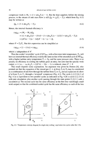
This result requires some explanation. An argument was given by Denton [6], who
pointed out that the expansion of the mixed gas (1 + +) from T5 to T6 may be considered
as a combination of unit flow through the turbine from T3 to T4, and an expansion of a flow
of +from T2 to TI, through a ‘reversed’ compressor (Fig. 4.2). The cycle [1,2,3,5,6,1] of
Fig. 4.2a is equivalent to two parallel cycles as indicated in Fig. 4.2b: a cycle [1,2,3,4,1]
with unit circulation; plus another cycle passing through the state points [1,2,2,1] with a
2 p
circulation $. The second cycle has the same efficiency as the first (but vanishingly small
work output) so that the combined cooled cycle has the same efficiency as each of the two
3
T T B
Y
T*
1
S
Fig. 4.2. Temperature-entropy diagram for single-step coolingquivalent two cycles (after Ref. [5]).