
Page 79 - Advanced Gas Turbine Cycles
P. 79
Chapter 4. Cycle eficiency with turbine cooling (cooling frow rates specified) 55
where & is the total amount of cooling air supplied from the compressor. The exhaust
temperature TE is therefore a function of & and, if I& is neglected, then it is given by
= TE/T~ = 1 + [(e - x)/x(~ + &)I = (e/x)(i - &) + k. (4.22)
This expression for & can also be obtained directly from Eqs. (4.16) and (4.19) [5].
4.2.2. Cooling of irreversible cycles
From the study of uncooled cycles in Chapter 3, we next move to consider irreversible
cycles with compressor and turbine isentropic efficiencies, qc and %, respectively.
The a/s efficiency of the irreversible uncooled cycle [CHTInr was given in Eq. (3.13) as
(rl)IU = [(a - x)(x - l)l/[X(P - 41, (4.23)
where a! = qcw8 and /3 = 1 + qc(8 - l), with 8 = T3/T,, and this will be used as a
comparator for the modified (cooled) cycles. As a numerical illustration, with
T3 = 1800K, TI = 300 K (8= 6.0), = 0.9, qc = 0.8, (Y = 4.32, and /3 = 5, the
uncooled thermal efficiency (q)nr is a maximum of 0.4442, at x = 2.79 (r = 36.27).
compared with the reversible efficiency, (v)~" = 0.642. The expression for efficiency,
Eq. (4.23), is modified when turbine cooling takes place.
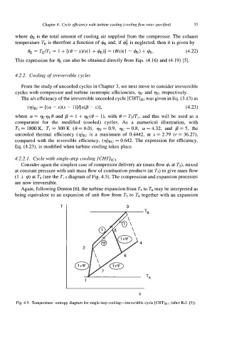
4.2.2.1. Cycle with single-step cooling [CHT],c,
Consider again the simplest case of compressor delivery air (mass flow $, at T2), mixed
at constant pressure with unit mass flow of combustion products (at T3) to give mass flow
(1 + I,+) at T5 (see the T, s diagram of Fig. 4.5). The compression and expansion processes
are now irreversible.
Again, following Denton [6], the turbine expansion from T5 to Ts may be interpreted as
being equivalent to an expansion of unit flow from T3 to T4 together with an expansion
3
1
~~ ~ ~
S
Fig. 4.5. Temperature-entropy diagram for single-step cooling-irreversible cycle [CHT],,-, (after Ref. [5]).