
Page 82 - Advanced Gas Turbine Cycles
P. 82
58 Advanced gas turbine cycles
4.2.2.3. Cycle with two step cooling [CHTIIC~
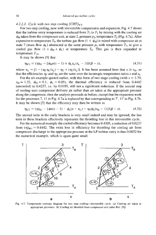
For two step cooling, now with irreversible compression and expansion, Fig. 4.7 shows
that the turbine entry temperature is reduced from T3 to T5 by mixing with the cooling air
&+ taken from the compressor exit, at state 2, pressurep2, temperature T2 (Fig. 4.7a). After
expansion to temperature T9, the turbine gas flow (1 + &+) is mixed with compressor air at
state 7 (mass flow JIL) abstracted at the same pressure p7 with temperature T7, to give a
cooled gas flow (1 + I+!+, + JIL) at temperature Ts. This gas is then expanded to
temperature Tl0.
It may be shown [5] that
-
7hc2 = (h~ - 1) + (CILEL(XL - I)I/(P - x), (4.31)
[&I&
where sL = [l - (m~/&~) - r)~ + (m/xL)]. It has been assumed here that x >> xH, so
that the efficiencies qc and are the same over the isentropic temperature ratios x and xL.
For the a/s example quoted earlier, with this form of two stage cooling (with x = 2.79,
xH = 1.22, &+ = 0.1, JIL = 0.05), the thermal efficiency is reduced from 0.4442
(uncooled) to 0.4257, i.e. by 0.0185, still not a significant reduction. If the second step
of cooling uses compressor delivery air rather than air taken at the appropriate pressure
along the compressor, then the analysis proceeds as before, except that the expansion work
for the processes 7, 11 in Fig. 4.7a is replaced by that corresponding to 7', 11' in Fig. 4.7b.
It may be shown [5] that the efficiency may then be written as
?hC2 = (7)lU - { @(x - 1) - &(E - EL) - mtk(xH - I)}/(@ - x). (4.32)
The second term in the curly brackets is very small indeed and may be ignored; the last
term in these brackets effectively represents the throttling loss in this irreversible cycle.
For the numerical example the cooled efficiency becomes 0.4205, a reduction of 0.0237
from (T/)~" = 0.4442. The extra loss in efficiency for throttling the cooling air from
compressor discharge to the appropriate pressure at the LP turbine entry is thus 0.0052 for
the numerical example, which is again quite small.
T 3 T 3
TB
S S
a b
Fig. 4.7. Temperam-entropy diagram for two step cooling-irreversible cycle. (a) Cooling air taken at
appropriate pressures. (b) Cooling air throttled from compressor exit (after Ref. [5]).