
Page 92 - Advanced Gas Turbine Cycles
P. 92
68 Advanced gas turbine cycles
45
30
Y
0 + UNCOOLED
20
15
lo00 12M) 1400 1600 1800 XI00 1200 2400 2600 2800
MAXIMUM TEMPERATURE K
COMBUSTION T, (UNCOOLED) OR ROTOR INLET T,(COOLED]
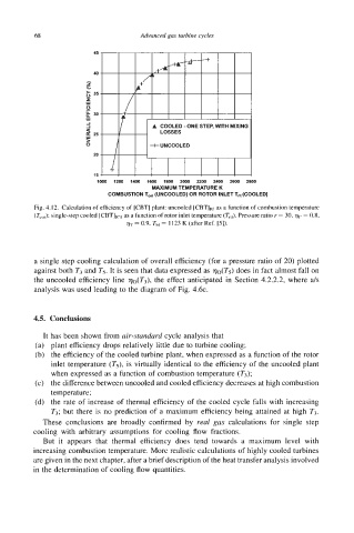
Fig. 4.1 2. Calculation of efficiency of [CBT] plant: uncooled [CBT]I~J as a function of combustion temperature
(Tco,); single-step cooled [CBTIlcl as a function of rotor inlet temperature (Tht). Pressure ratio r = 30, l)c = 0.8,
= 0.9, Thl = 1123 K (after Ref. [5]).
a single step cooling calculation of overall efficiency (for a pressure ratio of 20) plotted
against both T3 and T5. It is seen that data expressed as 77o(T5) does in fact almost fall on
the uncooled efficiency line v0(T3), the effect anticipated in Section 4.2.2.2, where a/s
analysis was used leading to the diagram of Fig. 4.6~.
4.5. Conclusions
It has been shown from air-standard cycle analysis that
(a) plant efficiency drops relatively little due to turbine cooling;
(b) the efficiency of the cooled turbine plant, when expressed as a function of the rotor
inlet temperature (T5), is virtually identical to the efficiency of the uncooled plant
when expressed as a function of combustion temperature (T3);
(c) the difference between uncooled and cooled efficiency decreases at high combustion
temperature;
(d) the rate of increase of thermal efficiency of the cooled cycle falls with increasing
T3; but there is no prediction of a maximum efficiency being attained at high T3.
These conclusions are broadly confirmed by real gas calculations for single step
cooling with arbitrary assumptions for cooling flow fractions.
But it appears that thermal efficiency does tend towards a maximum level with
increasing combustion temperature. More realistic calculations of highly cooled turbines
are given in the next chapter, after a brief description of the heat transfer analysis involved
in the determination of cooling flow quantities.