
Page 68 - Advanced Thermodynamics for Engineers, Second Edition
P. 68
3.4 REVERSED HEAT ENGINES 53
Temperature, T T 2 Q 3 T
-W
T T
1 4
Q
Specific entropy, s
FIGURE 3.18
T–s diagram for reversed heat engine (refrigerator or heat pump) operating on reversed Carnot cycle.
(a) (b)
System boundary System boundary
Evaporator Evaporator
Expander W Throttle
turbine Expander valve
Q in Q
Ice box Condenser Q out Ice box Condenser Q
W Pump Pump W Pump Pump
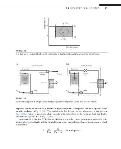
FIGURE 3.19
Schematic diagrams of refrigerator (or heat pump) (a) with expander turbine and (b) with throttle.
expander turbine. In most small, domestic, refrigeration plants, the expander turbine is replaced with a
throttle, as shown in Fig. 3.19(b). This modifies the T–s diagram for the refrigerator to that given in
Fig. 3.20(a). Many refrigeration plants operate with subcooling of the working fluid that further
modifies the cycle to that in Fig. 3.20(b).
As described in Section 2.7.1, thermal efficiency is not the correct parameter to define the ‘effi-
ciency’ of a reversed cycle, and the parameter used in this case is the coefficient of performance, which
is defined as
Q C Q C
; for a refrigerator
b ¼ ¼
W net Q H Q C