
Page 69 - Advanced Thermodynamics for Engineers, Second Edition
P. 69
54 CHAPTER 3 ENGINE CYCLES AND THEIR EFFICIENCIES
(a) (b)
Temperature, T Temperature, T
Q out Q out
2 3 3
T 3 T 3
Condensation 2 Condensation
Throttling Throttling
W C W C
Evaporation Evaporation
T 1 T 1
1 4 1 4
Q in Q in n
Saturated Saturated Saturated Saturated
liquid line vapour line liquid line vapour line
Specific entropy, s Specific entropy, s
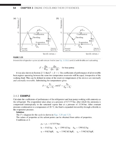
FIGURE 3.20
Irreversible refrigeration cycles (a) with simple throttle (see Fig. 3.19(b)) and (b) with throttle and subcooling.
Q H Q H
0 ; for heat pump:
b ¼ ¼
W net Q H Q C
It was also shown in Section 2.7.1 that b ¼ b þ 1. The coefficients of performance of all reversible
0
heat engines operating between the same two temperature reservoirs will be equal, irrespective of the
working fluid. This can be defined in terms of the reservoir temperatures if the devices are internally
and externally reversible. Substituting for temperatures gives
T C T H
:
0
b ¼ ; and b ¼
T H T C T H T C
3.4.3 EXAMPLE
Calculate the coefficients of performance of the refrigerator and heat pump working with ammonia as
the refrigerant. The evaporation takes place at a pressure of 0.7177 bar, after which the ammonia is
compressed isentropically to the saturated vapour line at a pressure of 15.54 bar. After constant
pressure condensation to a temperature of 28 C, the fluid is expanded irreversibly through a throttle to
the evaporator pressure.
Solution:
The T–s diagram for the cycle is shown in Figs. 3.20 and 3.21.
The values of properties at the salient points can be obtained from tables of properties.
Conditions at 4:
p 4 ¼ p 1 ¼ 0:7177 bar;
h f ¼ 0kJ=kg; h g ¼ 1390 kJ=kg; h fg ¼ 1390 kJ=kg:
s f ¼ 0kJ=kgK; s fg ¼ 5:962 kJ=kgK; s g ¼ 5:962 kJ=kgK: