
Page 147 - Advanced thermodynamics for engineers
P. 147
6.5 MORE COMPLEX EXAMPLE OF THE USE OF FTT 133
0.8
0.7
0.6
0.5
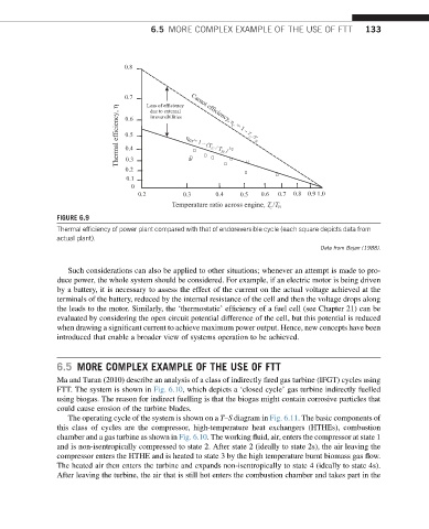
0.4 η er = 1 – (T C / T H ) 1/2
0.3
0.2
0.1
0
0.2 0.3 0.4 0.5 0.6 0.7 0.8
FIGURE 6.9
Thermal efficiency of power plant compared with that of endoreversible cycle (each square depicts data from
actual plant).
Data from Bejan (1988).
Such considerations can also be applied to other situations; whenever an attempt is made to pro-
duce power, the whole system should be considered. For example, if an electric motor is being driven
by a battery, it is necessary to assess the effect of the current on the actual voltage achieved at the
terminals of the battery, reduced by the internal resistance of the cell and then the voltage drops along
the leads to the motor. Similarly, the ‘thermostatic’ efficiency of a fuel cell (see Chapter 21) can be
evaluated by considering the open circuit potential difference of the cell, but this potential is reduced
when drawing a significant current to achieve maximum power output. Hence, new concepts have been
introduced that enable a broader view of systems operation to be achieved.
6.5 MORE COMPLEX EXAMPLE OF THE USE OF FTT
Ma and Turan (2010) describe an analysis of a class of indirectly fired gas turbine (IFGT) cycles using
FTT. The system is shown in Fig. 6.10, which depicts a ‘closed cycle’ gas turbine indirectly fuelled
using biogas. The reason for indirect fuelling is that the biogas might contain corrosive particles that
could cause erosion of the turbine blades.
The operating cycle of the system is shown on a T–S diagram in Fig. 6.11. The basic components of
this class of cycles are the compressor, high-temperature heat exchangers (HTHEs), combustion
chamber and a gas turbine as shown in Fig. 6.10. The working fluid, air, enters the compressor at state 1
and is non-isentropically compressed to state 2. After state 2 (ideally to state 2s), the air leaving the
compressor enters the HTHE and is heated to state 3 by the high temperature burnt biomass gas flow.
The heated air then enters the turbine and expands non-isentropically to state 4 (ideally to state 4s).
After leaving the turbine, the air that is still hot enters the combustion chamber and takes part in the