
Page 148 - Advanced thermodynamics for engineers
P. 148
134 CHAPTER 6 FINITE TIME (OR ENDOREVERSIBLE) THERMODYNAMICS
exhaust gas
6 High temperature
heat exchanger
2
3
5
Turbine
2 3
Compressor
5
1 4 4 Generator
Intake
air Fuel
Burner
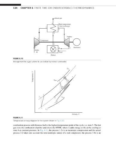
FIGURE 6.10
Arrangement for a gas turbine to use biofuel by indirect combustor.
T Hin
Temperature, T T Hout 3 5
4
4 S S S
2
2 S T Lout
6
1
T Lin
Entropy, S
FIGURE 6.11
Temperature-entropy diagram for the system shown in Fig. 6.10.
combustion process with biomass fuel to the highest temperature point of the cycle, i.e. state 5. The hot
gas exits the combustion chamber and enters the HTHE, where it adds energy to the air by cooling to
state 6 at constant pressure. In Fig. 6.11, the process 1-2s is an isentropic compression and the actual
process 1-2 takes into account the non-isentropic nature of a real compressor; the process 3-4s is an