
Page 375 - Advanced thermodynamics for engineers
P. 375
364 CHAPTER 16 RECIPROCATING INTERNAL COMBUSTION ENGINES
80
70
(%) 60
Brake thermal efficiency, η 40 Otto cycle
50
thermal efficiency
α = 40
30
α = 60
α = 140
20
10
0
0 2 4 6 8 10 12 14 16 18 20 22 24
Compression ratio, r (-)
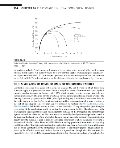
FIGURE 16.10
Variation of brake thermal efficiency with compression ratio. Maximum pressures ¼ 40, 60, 140 bar:
fmep ¼ 1 bar.
by modern standards. Petrol engines will normally be operating in the range of 60 bar peak pressure
whereas diesel engines will achieve values up to 140 bar (this applies to medium speed engines pro-
ducing around 1000–3000 kW). At these peak pressures, the optimum compression ratio will be in the
range 12:1 to 18:1. The effect of friction on the efficiency is less in this case because p is greater.
b
16.6 SIMULATION OF COMBUSTION IN SPARK-IGNITION ENGINES
Combustion processes were described in detail in Chapter 15, and the way in which these basic
principles apply in engines was discussed above. A simplified model of combustion in spark-ignition
engines, based on the paper by Benson et al. (1975), which includes constant pressure in the inlet and
exhaust manifolds, will be used here to investigate various parameters affecting engine ‘cycles’. The
resulting computer program, entitled SPIE (SPark Ignition Engine), is available in executable form for
the reader to use to perform his/her own investigations, and has been used to develop some problems at
the end of this chapter. This program can be accessed by visiting http://booksite.elsevier.com/
9780444633736/. While this section is based on the simulation of a spark-ignition (petrol) engine
cycle many of the conclusions would be similar for a compression ignition (diesel) engine. In the
spark-ignition engine combustion can be considered to be based on the propagation of a flame through
a premixed medium of fuel and air. The mixture can be formed by fuel injection equipment mounted in
the inlet manifold upstream of the inlet valve. In some engines currently under development injection
directly into the cylinder is used to introduce stratified combustion to allow the engine to operate at
lower overall air–fuel ratios. There are difficulties in achieving good combustion under all operating
conditions. A brief description of diesel engine combustion was given in Section 16.4, when it is stated
that the initial combustion is the spontaneous ‘explosion’ of the initially premixed fuel and air, fol-
lowed by the diffusion burning of the later fuel as it is injected into the cylinder. The examples dis-
cussed in Section 16.3 could be expanded to consider the flow of gases into and out of the cylinder, but