
Page 485 - Advanced thermodynamics for engineers
P. 485
20.6 THERMOELECTRICITY – THE APPLICATION OF IRREVERSIBLE 477
Hence
Q ¼ TS (20.47)
Equation (20.47) is interesting because it retains the basic generic form relating ‘heat’, tempera-
ture, and ‘entropy’, namely that entropy is evaluated by dividing a heat transfer term by a temperature
term.
It is now possible to relate the equations derived above to the various physical phenomena observed
in experiments. Previously the Seebeck effect was defined as the potential difference set up in a wire
due to a temperature gradient without any current flow (i.e. ðdε=dTÞ ). From Eqn (20.44), if there is
J I¼0
zero current flow
dT dε dε
S ¼ or ¼ S (20.48)
d‘ d‘ dT
Hence, S* is a measure of the magnitude of the Seebeck effect, and the value of S* for most
materials is nonzero.
If the wire is kept at a constant temperature, a flow of heat (thermal energy) will occur due to the
electrical potential difference. From Eqn (20.43)
dε
J Q ¼ lTS (20.49)
d‘
This transport of thermal energy due to an electrical field is known as the Thomson effect.
20.6.4 THE THERMOCOUPLE
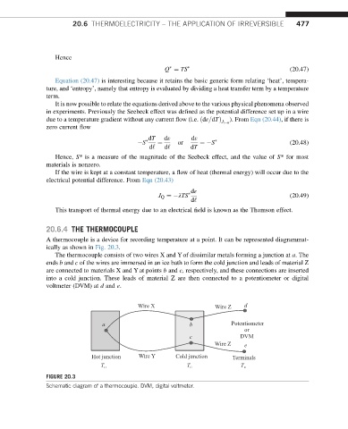
A thermocouple is a device for recording temperature at a point. It can be represented diagrammat-
ically as shown in Fig. 20.3.
The thermocouple consists of two wires X and Y of dissimilar metals forming a junction at a. The
ends b and c of the wires are immersed in an ice bath to form the cold junction and leads of material Z
are connected to materials X and Y at points b and c, respectively, and these connections are inserted
into a cold junction. These leads of material Z are then connected to a potentiometer or digital
voltmeter (DVM) at d and e.
Wire X Wire Z d
a b Potentiometer
or
c DVM
Wire Z e
Hot junction Wire Y Cold junction Terminals
T H T C T R
FIGURE 20.3
Schematic diagram of a thermocouple. DVM, digital voltmeter.