Page 487 - Advanced thermodynamics for engineers
P. 487

20.6 THERMOELECTRICITY – THE APPLICATION OF IRREVERSIBLE             479


               are both made of the same material. Since S* is defined in terms of J S and J I it is independent of the
               length of the constituent wires, and hence the emf generated is also independent of the length of the
               wires.
                  Thermocouples are normally bought as pairs of wires which have been calibrated by experimental
               tests. For low temperatures (up to 150 C) Cu-Ni thermocouples may be used, for high temperatures

               platinum–rhodium is used. The calibration of the thermocouple is dependent only on the wires used to
               make the junctions; the length of thermocouples is not a parameter in the calibration, see Eqns (20.50)
               and (20.52a).

               20.6.4.1 Thermocouple with junctions at T C and T H and connections
                        in one of the measuring wires
               Figure 20.3 showed an idealised thermocouple in which the connections between the thermoelectric
               pair of wires and those connecting the thermocouple to the measuring device were maintained at the
               cold junction temperature. It might be inconvenient to set up the thermocouple in this way, and a more
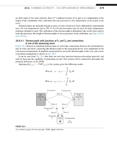
               convenient arrangement is shown in Fig. 20.4.
                  It can be seen from Fig. 20.4 that there are now four junctions between dissimilar materials, and
               each of these has the capability of generating an emf. This system will be analysed to determine the
               potential difference at the DVM.

                  Applying dεÞ J I ¼0  ¼ S dTÞ J I ¼0  to the system gives the following results.
                                                              T
                                                              Z R 0
                                           Wire dc  ε c   ε d ¼   S dT

                                                                  Z
                                                              T R
                                                               T
                                                              Z H
                                           Wire ca  ε a   ε c ¼   S dT

                                                                  Y
                                                             T R 0
                                            Hot junction  Cold junction
                                                     Wire X
                                       Hot                                Cold
                                   reservoir                           reservoir
                                           a                        b
                                      T H                                T C
                                                 Wire Y   Wire Y
                                                     c     e
                                         Connections
                                            T R'
                                                Wire Z      Wire Z
                                                      d  f
                                              Terminals
                                                T R   123.4  Potentiometer
                                                                      or
                                                                   DVM
               FIGURE 20.4
               Conventional layout of thermocouple. DVM, digital voltmeter.
   482   483   484   485   486   487   488   489   490   491   492