
Page 492 - Advanced thermodynamics for engineers
P. 492
484 CHAPTER 20 IRREVERSIBLE THERMODYNAMICS
20.7 DIFFUSION AND HEAT TRANSFER
20.7.1 BASIC PHENOMENA INVOLVED
The classical law of diffusion is due to Fick (1856). This states that the diffusion rate is proportional to
the concentration gradient, and is the mass transfer analogy of the thermal conduction law. The constant
of proportionality in Fick’s law is called the diffusion coefficient. It was found from experimental
evidence that the diffusion coefficient tended to vary with conditions and that better proportionality
could be obtained if the rate of diffusion was related to the gradient of chemical potential; this law is due
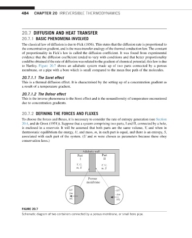
to Hartley. Figure 20.7 shows an adiabatic system made up of two parts connected by a porous
membrane, or a pipe with a bore which is small compared to the mean free path of the molecules.
20.7.1.1 The Soret effect
This is a thermal diffusion effect. It is characterised by the setting up of a concentration gradient as
a result of a temperature gradient.
20.7.1.2 The Dufour effect
This is the inverse phenomena to the Soret effect and is the nonuniformity of temperature encountered
due to concentration gradients.
20.7.2 DEFINING THE FORCES AND FLUXES
To choose the forces and fluxes, it is necessary to consider the rate of entropy generation (see Section
20.4, and de Groot (1951)). Suppose that a system comprising two parts, I and II, connected by a hole,
is enclosed in a reservoir. It will be assumed that both parts are the same volume, V, and when in
thermostatic equilibrium the energy, U, and mass, m, in each part is equal, and there is an entropy, S,
associated with each part of the system. (U and m were chosen as parameters because these obey
conservation laws.)
Adiabatic wall
Part Part
I II
V, U, V, U,
m, S m, S
Porous
membrane
U U
m m
S S
FIGURE 20.7
Schematic diagram of two containers connected by a porous membrane, or small bore pipe.