
Page 77 - Advanced thermodynamics for engineers
P. 77
62 CHAPTER 4 AVAILABILITY AND EXERGY
where
pAdx ¼ pdV ¼ dW sys ¼ work done by the fluid in the system;
Fdx ¼ dW use ¼ work done against the resisting force;
p 0 Adx ¼ p 0 dV ¼ dW surr ¼ work done against the surroundings:
Hence the work done by the system is not all converted into useful work, but some of it is used to do
displacement work against the surroundings, i.e.
dW sys ¼ dW use þ dW surr (4.3)
which can be rearranged to give
dW use ¼ dW sys dW surr : (4.4)
4.2 AVAILABILITY
It was shown above that not all the displacement work done by a system is available to do useful work.
This concept will now be generalised to consider all the possible work outputs from a system which is
not in thermodynamic and mechanical equilibrium with its surroundings (i.e. not at the ambient or
dead-state conditions).
Consider the system introduced earlier to define Helmholtz and Gibbs energy: this is basically the
method which was used to prove the Clausius inequality.
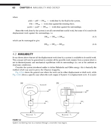
Fig. 4.2(a) shows the general case where the work can be either displacement or shaft work, while
Fig. 4.2(b) shows a specific case where the work output of System A is displacement work. It is easier
(a) (b)
System B
System B
System A System A
δ W δ W
p
T p
0
δ Q δ Q
δ W R δ W R
E R E R
δ Q δ Q 0
0
Reservoir T 0 Reservoir T 0
FIGURE 4.2
System transferring heat to a reservoir through a reversible heat engine.