
Page 164 - Advanced Mine Ventilation
P. 164
144 Advanced Mine Ventilation
10.3.2 Water Scrubbers
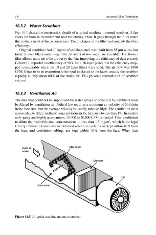
Fig. 10.5 shows the construction details of a typical machine-mounted scrubber. A fan
sucks air from inlets under and near the cutting drum. It goes through the filter panel
that collects most of the airborne dust. The thickness of the filter bed controls the filter
efficiency.
Original scrubbers had 40 layers of stainless steel mesh knit from 85 mm wires, but
today thinner filters containing 10 to 30 layers of wire mesh are available. The thinner
filter allows more air to be drawn by the fan, improving the efficiency of dust control.
Colinet [7] reported an efficiency of 90% for a 30-layer panel, but the efficiency drop-
ped considerably when the 10 and 20 layer filters were tried. The air flow was 8500
CFM. It has to be in proportion to the total intake air to the faces; usually the scrubber
capacity is only about 60% of the intake air. This prevents recirculation of scrubber
exhaust.
10.3.3 Ventilation Air
The dust that could not be suppressed by water sprays or collected by scrubbers must
be diluted by ventilation air. Federal law requires a minimum air velocity of 60 ft/min
in the face area, but the average velocity is usually twice as high. The ventilation air is
also needed to dilute methane concentrations in the face area to less than 1%. In moder-
ately gassy and highly gassy mines, 15,000 to 20,000 CFM is needed. This is sufficient
3
to dilute the respirable dust concentrations to less than 1.5 mg/m , which is the legal
US requirement. Best results are obtained when line curtains are kept within 10 ft from
the face, and ventilation tubings are kept within 15 ft from the face. When face
Figure 10.5 A typical machine-mounted scrubber.