
Page 194 - Advanced Mine Ventilation
P. 194
174 Advanced Mine Ventilation
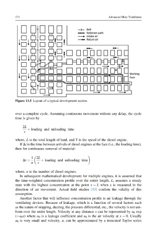
Figure 11.5 Layout of a typical development section.
over a complete cycle. Assuming continuous movement without any delay, the cycle
time is given by
2L
þ loading and unloading time
v
where, L is the total length of haul, and V is the speed of the diesel engine.
If Dt is the time between arrivals of diesel engines at the face (i.e., the loading time),
then for continuous removal of material:
1 2L
Dt ¼ þ loading and unloading time
n v
where, n is the number of diesel engines.
In subsequent mathematical development for multiple engines, it is assumed that
the time-weighted concentration profile over the entire length, L, assumes a steady
state with the highest concentration at the point x ¼ L when x is measured in the
direction of air movement. Actual field studies [10] confirm the validity of this
assumption.
Another factor that will influence concentration profile is air leakage through the
ventilating devices. Because of leakage, which is a function of several factors such
as the nature of stopping, ducting, the pressure differential, etc., the velocity is not uni-
form over the entire length. Velocity at any distance x can be represented by u 0 exp
( a 0 x) where a 0 is a leakage coefficient and u 0 is the air velocity at x ¼ 0. Usually
a 0 is very small and velocity, u, can be approximated by a truncated Taylor series