
Page 81 - Advanced Mine Ventilation
P. 81
64 Advanced Mine Ventilation
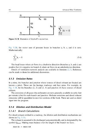
Figure 5.2 B Illustration of Kirchoff’s second law.
Fig. 5.2B, the vector sum of pressure losses in branches a, b, c, and d is zero.
Mathematically:
4
X
h i ¼ 0 (5.4)
i¼1
The head losses where air flows in a clockwise direction (branches a, b, and c) are
positive but it is negative in branch d where air flows in an anticlockwise direction.
Details of ventilation network analysis are available in literature [2,3]. Reference
can be made to them for additional discussions.
5.1.3 Emission Rates
In a mine, the branches and junction where sources of diesel exhaust are located are
known a priori. These are the haulage roadways and face areas. For example, in
Fig. 5.1B, let the branches (2, 3) and (3, 4) and junction (4) have sources of diesel
exhaust.
The emissions of all gases (the pollutants) are now generally available in cubic feet
per minute (cfm) for each branch and junction. Methane emissions and diesel exhaust
emissions will be quantified in next two sections of the book. These are used as direct
input into the program.
5.1.4 Dilution and Distribution Model
5.1.4.1 Branch Calculations
For diesel exhaust emitted in a roadway, the dilution and distribution mechanisms are
shown in Fig. 5.3A.
The exhaust is assumed to be discharged axisymmetrically and is designated by the
symbol Q dwall . Making mass balance over the length of the branch we have:
mass in ¼ mass out