
Page 82 - Advanced Mine Ventilation
P. 82
Ventilation Network Analysis 65
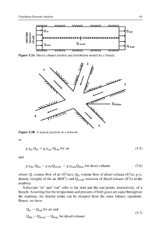
Figure 5.3A Diesel exhaust dilution and distribution model for a branch.
Figure 5.3B A typical junction in a network.
or
g r Q ¼ g r ,Q for air (5.5)
in in out out
and
g r din Q din þ g r Q dwall ¼ g r dout Q dout for diesel exhaust (5.6)
D
3
3
where: Q, volume flow of air (ft /sec); Q d , volume flow of diesel exhaust (ft /s); g,r,
3
3
density (weight) of the air (lb/ft ); and Q dwall , emission of diesel exhaust (ft /s) in the
roadway.
Subscripts “in” and “out” refer to the start and the end points, respectively, of a
branch. Assuming that the temperature and pressure of both gases are equal throughout
the roadway, the density terms can be dropped from the mass balance equations.
Hence, we have:
Q ¼ Q out for air and
in
(5.7)
Q din þ Q dwall ¼ Q dout for diesel exhaust.