
Page 131 - Advances In Productive, Safe, and Responsible Coal Mining
P. 131
Developing effective proximity detection systems for underground coal mines 115
3 9
5 7
10
2
1 4 6
8
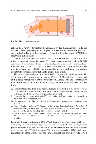
Fig. 7.7 iPD 1 zone configuration.
referred to as “iPD 1” throughout the remainder of this chapter. Zones 1 and 2 are
dynamic, meaning that they follow the position of the conveyor boom as it pivots lat-
erally to load coal onto haulage equipment. Zones 3 to 10 are based on the CMM chas-
sis (frame) and are static.
Each zone is associated with a set of CMM functions that are disabled whenever a
miner is detected within that zone. This zone layout was designed by NIOSH
researchers as an example of one potential configuration for selective machine func-
tion shutdown [15,18–21]. These 10 zones were created to capture all possible
machine motions that could affect a given location, and to provide zone logic to allow
operators to perform actions that would not put them at risk.
The second zone configuration is shown in Fig. 7.8, and will be referred to as “iPD
2” throughout the remainder of this chapter. Zones 1, 2, 11, and 12 are dynamic and
change based on the position of the conveyor boom. Zones 3 to 10 and 13 are based on
the CMM chassis and are static. Some of the major differences between iPD 1 and iPD
2 are:
1. Functions blocked by Zones 1 and 2 in iPD 2 depend on the position of the conveyor swing.
If the conveyor is centered (within some preselected tolerance), blocked functions are less
restrictive than if the conveyor is swung either left or right.
2. Forward and reverse tram functions in iPD 2 are blocked for Zones 4 to 9 to prevent accidents
when a miner is beside the CMM.
7. All tram functions in iPD 2 are blocked for Zones 6 and 7 to prevent any unsafe pivoting
motions.
4. Zone 11 has been added to iPD 2 to account for the area that exists between Zones 1 and 2
around the conveyor boom. This prevents any unsafe conveyor boom motions when an oper-
ator is near the tail by providing a buffer between Zones 1 and 2.
5. Zones 12 and 13 have been added to iPD 2 to account for a miner being on top of the CMM.
These zones were added to account for fatalities involving maintenance on top of the
machine.
Results of this study indicate that 82% of fatalities could have been prevented by con-
ventional proximity detection systems. The two different iPD zone configurations
presented illustrate different factors that affect performance and both were analyzed
over the same set of 39 fatal accidents. This analysis showed that iPD 2 could have
prevented 82% of the fatality cases (the same as conventional proximity), while iPD 1