
Page 145 - Advances In Productive, Safe, and Responsible Coal Mining
P. 145
Communication and tracking system performance 129
be evaluated. When accurate values of CAD entity parameters are determined, the
simulation and calculations of metric values for different tracking system configura-
tions may help optimize system design to meet tracking system requirements.
One of the main objectives of the author was to achieve tracking coverage in pri-
mary and secondary EWs and typical strategic areas in the study portion of the Test
Mine, and generally, to get signal into the belt entry, which is not an escapeway in the
Example Mine. The Test System layout for the Example Mine was designed by the
vendor to provide radio coverage to meet communication and tracking standards
set by MSHA.
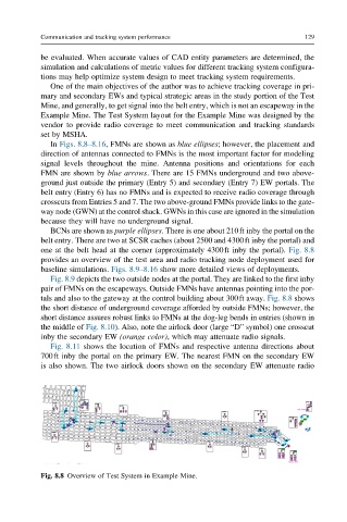
In Figs. 8.8–8.16, FMNs are shown as blue ellipses; however, the placement and
direction of antennas connected to FMNs is the most important factor for modeling
signal levels throughout the mine. Antenna positions and orientations for each
FMN are shown by blue arrows. There are 15 FMNs underground and two above-
ground just outside the primary (Entry 5) and secondary (Entry 7) EW portals. The
belt entry (Entry 6) has no FMNs and is expected to receive radio coverage through
crosscuts from Entries 5 and 7. The two above-ground FMNs provide links to the gate-
way node (GWN) at the control shack. GWNs in this case are ignored in the simulation
because they will have no underground signal.
BCNs are shown as purple ellipses. There is one about 210ft inby the portal on the
belt entry. There are two at SCSR caches (about 2500 and 4300ft inby the portal) and
one at the belt head at the corner (approximately 4300ft inby the portal). Fig. 8.8
provides an overview of the test area and radio tracking node deployment used for
baseline simulations. Figs. 8.9–8.16 show more detailed views of deployments.
Fig. 8.9 depicts the two outside nodes at the portal. They are linked to the first inby
pair of FMNs on the escapeways. Outside FMNs have antennas pointing into the por-
tals and also to the gateway at the control building about 300ft away. Fig. 8.8 shows
the short distance of underground coverage afforded by outside FMNs; however, the
short distance assures robust links to FMNs at the dog-leg bends in entries (shown in
the middle of Fig. 8.10). Also, note the airlock door (large “D” symbol) one crosscut
inby the secondary EW (orange color), which may attenuate radio signals.
Fig. 8.11 shows the location of FMNs and respective antenna directions about
700ft inby the portal on the primary EW. The nearest FMN on the secondary EW
is also shown. The two airlock doors shown on the secondary EW attenuate radio
Fig. 8.8 Overview of Test System in Example Mine.