
Page 141 - Advances In Productive, Safe, and Responsible Coal Mining
P. 141
Communication and tracking system performance 125
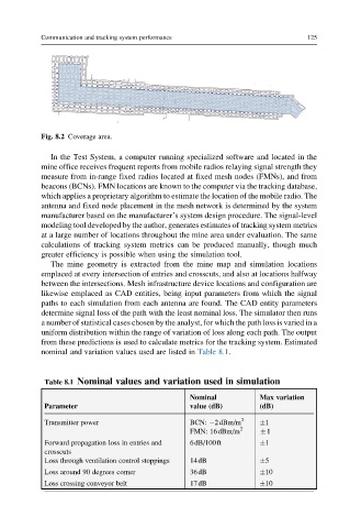
Fig. 8.2 Coverage area.
In the Test System, a computer running specialized software and located in the
mine office receives frequent reports from mobile radios relaying signal strength they
measure from in-range fixed radios located at fixed mesh nodes (FMNs), and from
beacons (BCNs). FMN locations are known to the computer via the tracking database,
which applies a proprietary algorithm to estimate the location of the mobile radio. The
antenna and fixed node placement in the mesh network is determined by the system
manufacturer based on the manufacturer’s system design procedure. The signal-level
modeling tool developed by the author, generates estimates of tracking system metrics
at a large number of locations throughout the mine area under evaluation. The same
calculations of tracking system metrics can be produced manually, though much
greater efficiency is possible when using the simulation tool.
The mine geometry is extracted from the mine map and simulation locations
emplaced at every intersection of entries and crosscuts, and also at locations halfway
between the intersections. Mesh infrastructure device locations and configuration are
likewise emplaced as CAD entities, being input parameters from which the signal
paths to each simulation from each antenna are found. The CAD entity parameters
determine signal loss of the path with the least nominal loss. The simulator then runs
a number of statistical cases chosen by the analyst, for which the path loss is varied in a
uniform distribution within the range of variation of loss along each path. The output
from these predictions is used to calculate metrics for the tracking system. Estimated
nominal and variation values used are listed in Table 8.1.
Table 8.1 Nominal values and variation used in simulation
Nominal Max variation
Parameter value (dB) (dB)
Transmitter power BCN: 2dBm/m 2 1
FMN: 16dBm/m 2 1
Forward propagation loss in entries and 6dB/100ft 1
crosscuts
Loss through ventilation control stoppings 14dB 5
Loss around 90 degrees corner 36dB 10
Loss crossing conveyor belt 17dB 10