
Page 119 - Advances in bioenergy (2016)
P. 119
59
is given in a recent publication. Several laboratory catalytic pyrolysis/upgrading experiments
are reported. In general, it seems that the most efficient process technology for biomass
pyrolysis is based on fluid bed reactors. Biomass particles are introduced into a bed of hot
sand, fluidized by a gas, which is usually a recirculated product gas. High heat transfer rates
from fluidized sand result in the rapid heating of biomass particles. This process has been
proved as very efficient for maximum bio-oil yield and for this reason it has been scaled up by
59
companies such as Dynamotive. This technology, although suitable for the conventional
biomass technology, is difficult to be applied for biomass catalytic pyrolysis. The reason is
that catalyst deactivation usually takes place during catalytic pyrolysis that makes the catalyst
inactive within very short time. Thus, even by replacing the inert heat carrier by a catalytic
material, the life of this material will be limited as very rapidly the catalyst will be
deactivated and will behave as an inert material. This technology can be used for downstream
upgrading of bio-oil vapors by putting a fixed or fluid bed of a catalyst at the reactor exit.
However, again catalyst deactivation in this second bed can be a serious issue, except if the
catalyst could be continuously replaced.
The most appropriate process for biomass catalytic pyrolysis should be based on the
circulating fluid bed (CFB) technology that includes a regeneration step for the continuous
catalyst regeneration. In this way, the catalyst is mixed with the biomass particles always in an
active state. The technology is similar to fluid catalytic cracking (FCC) process that is the
biggest conversion unit in a refinery for the conversion of heavy hydrocarbons to lighter fuels.
Ensyn, CPERI, and KiOR have developed technology for CFB pyrolysis. 59-61 The rotating cone
62
technology developed by BTG works also in the circulating mode. Commercial CFB
technology for biomass catalytic pyrolysis is not available today. However, it has been proved
in pilot scale, while currently demonstration scales are investigated. KiOR develops
technology on biomass catalytic pyrolysis and they are today in a demonstration phase
producing 15 barrels per day bio-crude. KiOR granted funding for the construction of five
59
commercial plants in Mississippi based on its technology. The success of these commercial
plants will open new horizons in the establishment of biomass catalytic pyrolysis process.
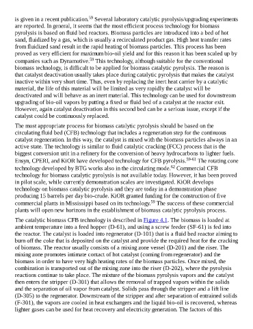
The catalytic biomass CFB technology is described in Figure 4.1. The biomass is loaded at
ambient temperature into a feed hopper (D-61), and using a screw feeder (SF-61) is fed into
the reactor. The catalyst is loaded into regenerator (D-101) that is a fluid bed reactor aiming to
burn off the coke that is deposited on the catalyst and provide the required heat for the cracking
of biomass. The reactor usually consists of a mixing zone vessel (D-201) and the riser. The
mixing zone promotes intimate contact of hot catalyst (coming from regenerator) and the
biomass in order to have very high heating rates of the biomass particles. Once mixed, the
combination is transported out of the mixing zone into the riser (D-202), where the pyrolysis
reactions continue to take place. The mixture of the biomass pyrolysis vapors and the catalyst
then enters the stripper (D-301) that allows the removal of trapped vapors within the solids
and the separation of oil vapor from catalyst. Solids pass through the stripper and a lift line
(D-305) to the regenerator. Downstream of the stripper and after separation of entrained solids
(F-301), the vapors are cooled in heat exchangers and the liquid bio-oil is recovered, whereas
lighter gases can be used for heat recovery and electricity generation. The factors of this