
Page 120 - Advances in bioenergy (2016)
P. 120
technology leading to an optimum bio-oil yield include the type of catalyst, the reactor design,
the residence time in the reactor, the fast separation of the solid, and the vapors in stripper and
the fast quench of the produced vapors in the heat exchangers.
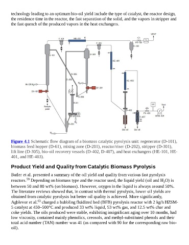
Figure 4.1 Schematic flow diagram of a biomass catalytic pyrolysis unit: regenerator (D-101),
biomass feed hopper (D-61), mixing zone (D-201), reactor/riser (D-202), stripper (D-301),
lift line (D-305), bio-oil recovery vessels (D-402, D-407), and heat exchangers (HE-101, HE-
401, and HE-403).
Product Yield and Quality from Catalytic Biomass Pyrolysis
Butler et al. presented a summary of the oil yield and quality from various fast pyrolysis
59
reactors. Depending on biomass type and the reactor used, the liquid yield (oil and H O) is
2
between 50 and 80 wt% (on biomass). However, oxygen in the liquid is always around 50%.
The literature reviews showed that, in contrast with thermal pyrolysis, lower oil yields are
obtained from catalytic pyrolysis but better oil quality is achieved. More significantly,
63
Agblevor et al. charged a bubbling fluidized bed (BFB) pyrolysis reactor with 2 kg/h HZSM-
5 catalyst at 450–500°C and produced 33 wt% liquid, 53 wt% gas, and 12.5 wt% char and
coke yields. The oils produced were stable, exhibiting insignificant aging over 10 months, had
low viscosity, contained mainly phenolics, creosols, and methyl-substituted phenols and their
total acid number (TAN) number was 41 (as compared with 90 for the corresponding raw bio-
oil).