
Page 49 - Advances in Biomechanics and Tissue Regeneration
P. 49
3.2 IDEAL MECHANICAL PROPERTIES FOR COLONIC STENTS 43
Wallstent, braided, Song, and Esophacoil stents are based on this mechanism. The Esophacoil stent is, in fact, a sim-
ple helicoidal spring, while the others are two layers of helicoidal springs turned in reverse with sliding knots between
the wires. In this case, the number of wires per layer is another design parameter.
3.2.3.1.2 RADIAL SPRING
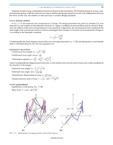
In Fig. 3.11A, the analyzed case corresponds to a Z shape. The design parameters are: pitch (h), diameter (D), wire
diameter (d), and number of circumference divisions (n). Again, a nonlinear inverse problem must be solved to deter-
mine the stiffness of the stent corresponding to every expanded configuration. By assuming that under small loads the
total length of the arm between knots (L) remains unchanged, then changes in D must be accommodated by changes in
h according to the kinematic constraint
r ffiffiffiffiffiffiffiffiffiffiffiffiffiffiffiffiffiffiffiffi 2
2
π D
2
h +
4n
L ¼ 2
Considering the free-body diagram of one-half of one wire ring in the stent (Fig. 3.11B), and taking into account that the
stent is unloaded along its axis, the next equations are:
KINEMATICS RELATIONS q ffiffiffiffiffiffiffiffiffiffiffiffiffiffiffiffiffi
2
h + π D 2
2
Undeformed truss length: L 0 ¼ 4n 2
πD
Undeformed truss angle: tanα 0 ¼ 2nh
x x
2 3
Deformation equation: y ¼ δ 1 3 +2
L L
where δ is perpendicular displacement to the truss; L is the distance between the ends of truss; and x is the coordinate in
the direction of the length.
R L q ffiffiffiffiffiffiffiffiffiffiffiffiffi 2
1+ y’ dx
Deformed truss length: L d ¼
0
π D + ΔDÞ
ð
Deformed truss angle: tanα ¼
ð
2nh ΔhÞ
πΔD cosα
2n
Perpendicular displacement to truss: δ ¼
q ffiffiffiffiffiffiffiffiffiffiffiffiffiffiffiffiffiffiffiffiffiffiffiffiffiffiffiffiffiffiffiffiffiffiffiffiffiffiffiffiffi
2 2
h ΔhÞ + π 2 D + ΔDÞ
ð
4n 2
Distance between ends of truss: L ¼ ð
STATIC EQUILIBRIUM
Equilibrium in half spring (Fig. 3.11B).
D + ΔD
2
Shear force: V ¼ p 0 h Δhð Þ
FIG. 3.11 Radial spring: (A) design parameters; (B) free-body diagram.
I. BIOMECHANICS