
Page 48 - Advances in Biomechanics and Tissue Regeneration
P. 48
42 3. DESIGN, SIMULATION, AND EXPERIMENTATION OF COLONIC STENTS
By assuming that under small loads the total length of the wire (L) remains unchanged, then changes in D must be
accommodated by changes in h according to the constraint:
p ffiffiffiffiffiffiffiffiffiffiffiffiffiffiffiffiffiffiffi
2
2
L ¼ h + π D 2
KINEMATICS RELATIONS
p ffiffiffiffiffiffiffiffiffiffiffiffiffiffiffiffiffiffiffi
2
2
Undeformed spiral length: L 0 ¼ h + π D 2
h
Reference angle: tanα 0 ¼ D q ffiffiffiffiffiffiffiffiffiffiffiffiffiffiffiffiffiffiffiffiffiffiffiffiffiffiffiffiffiffiffiffiffiffiffiffiffiffiffiffiffiffiffiffiffiffiffiffi
2 2 2
Deformed spiral length: L ¼ ð h ΔhÞ + π D + ΔDÞ
ð
h Δh
Deformed reference angle: tanα ¼ D + ΔD
Angle increment: Δα¼α 0 α
Δα
Angle per unit length: θ ¼ L
h
0
Undeformed spiral slope: tanβ ¼ πD
h Δh
Deformed spiral slope: tanβ ¼
π D + ΔDÞ
ð
STATIC EQUILIBRIUM
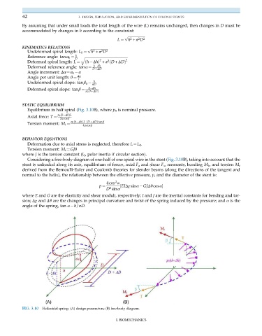
Equilibrium in half spiral (Fig. 3.10B), where p 0 is nominal pressure.
p 0 h ΔhÞL
ð
2πcosβ
Axial force: T ¼
p 0 h ΔhÞLD + ΔDÞtanβ
ð
ð
4πcosβ
Torsion moment: M t ¼
BEHAVIOR EQUATIONS
Deformation due to axial stress is neglected, therefore L¼L 0 .
Torsion moment: M t ¼GJθ
where J is the torsion constant (I 0 , polar inertia if circular section).
Considering a free-body diagram of one-half of one spiral wire in the stent (Fig. 3.10B), taking into account that the
stent is unloaded along its axis, equilibrium of forces, axial F a and shear F s , moments, bending M b , and torsion M t
derived from the Bernoulli-Euler and Coulomb theories for slender beams (along the directions of the tangent and
normal to the helix), the relationship between the effective pressure, p, and the diameter of the stent is:
4cos α
2
D sinα
p ¼ 2 ½ EIΔχ sinα GJΔϑcosα
where E and G are the elasticity and shear moduli, respectively; I and J are the inertial constants for bending and tor-
sion; Δχ and Δϑ are the changes in principal curvature and twist of the spring induced by the pressure; and α is the
angle of the spring, tan α¼h/πD.
FIG. 3.10 Helicoidal spring: (A) design parameters; (B) free-body diagram.
I. BIOMECHANICS