
Page 202 - Advances in Renewable Energies and Power Technologies
P. 202
3. Necessity of Joint Adoption of Distributed Maximum Power Point 175
By Substituting Eq. (5.10) in (5.9), we get
P pan1 max
v ds max $ 1
P pan1
V out lim 0 1
DP tot
B C
1
B C
@ P pan1 A
N$V OC $ (5.11)
v ds max
DP pan1 max
v ds max $ 1
P pan1
¼
ð
v ds max $ N 2Þ$DP tot
1
N$V OC $P pan1
where P pan1 is the maximum power that can be extracted from the first PV module.
An additional constraint must be considered in the case of boost-based LSCPVUs. In
fact, because the voltage conversion ratio of the boost converter is higher than 1 and
the operating voltage of a given PV module is comprised between 0 and V oc , in addi-
tion to Eq. (5.11) it must also be:
V out lim V OC (5.12)
3.1.2 CMPPTS Technique
The CMPPTS technique is based on the periodic scan of the PeV characteristic of
the string of N LSCPVUs to identify the value V b opt of the bulk inverter voltage v b in
correspondence of which the power P extracted from the string of LSCPVUs as-
sumes its maximum value. The scan is carried out by means of the CMPPTS
controller and by means of the inverter outer feedback loop (Fig. 5.2). The output
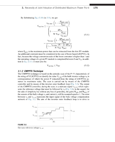
of the CMPPTS controller, during the scan, is a staircase signal v b ref , which repre-
sents the reference voltage that must be followed by v b (Fig. 5.6). In the sequel, for
the sake of simplicity but without any loss of generality, the gains H bulk and R bulk of
the sensors of the bulk voltage v b and current i b will be assumed equal to 1. The error
between v b and v b ref represents the input signal of the bulk voltage compensation
network of Fig. 5.2. The aim of the inverter outer feedback loop is to drive to
V b – max
[V] V b – ref V b – opt
T b
V b – min
n∙T b
[S]
FIGURE 5.6
Staircase reference voltage v b ref .